Thank you for choosing an Adastra LA series induction loop amplifier for
your assisted hearing installation.
This unit is designed to offer high quality hearing assistance for
hearing aid users.
Note: All induction loops in the UK should be installed in accordance
with BS7594.
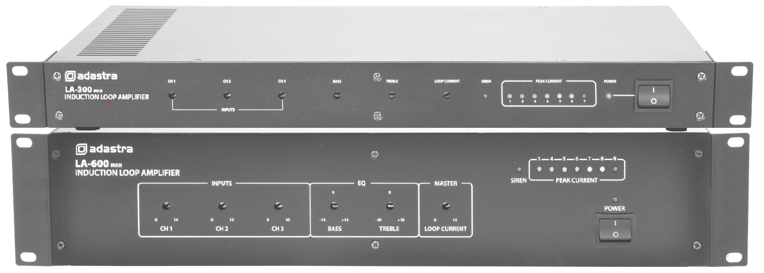
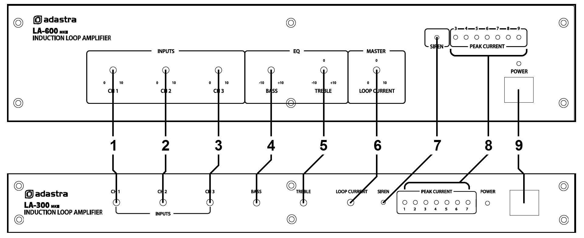
Front panel
|
|
|
|
| 1. |
Channel 1 input level control |
6. |
Loop current (master level) control |
| 2. |
Channel 2 input level control |
7. |
Siren indicator |
| 3. |
Channel 3 input level control |
8. |
Loop current level indicator |
| 4. |
Bass EQ adjustment |
9. |
Power switch and indicator |
| 5. |
Treble EQ adjustment |
|
|
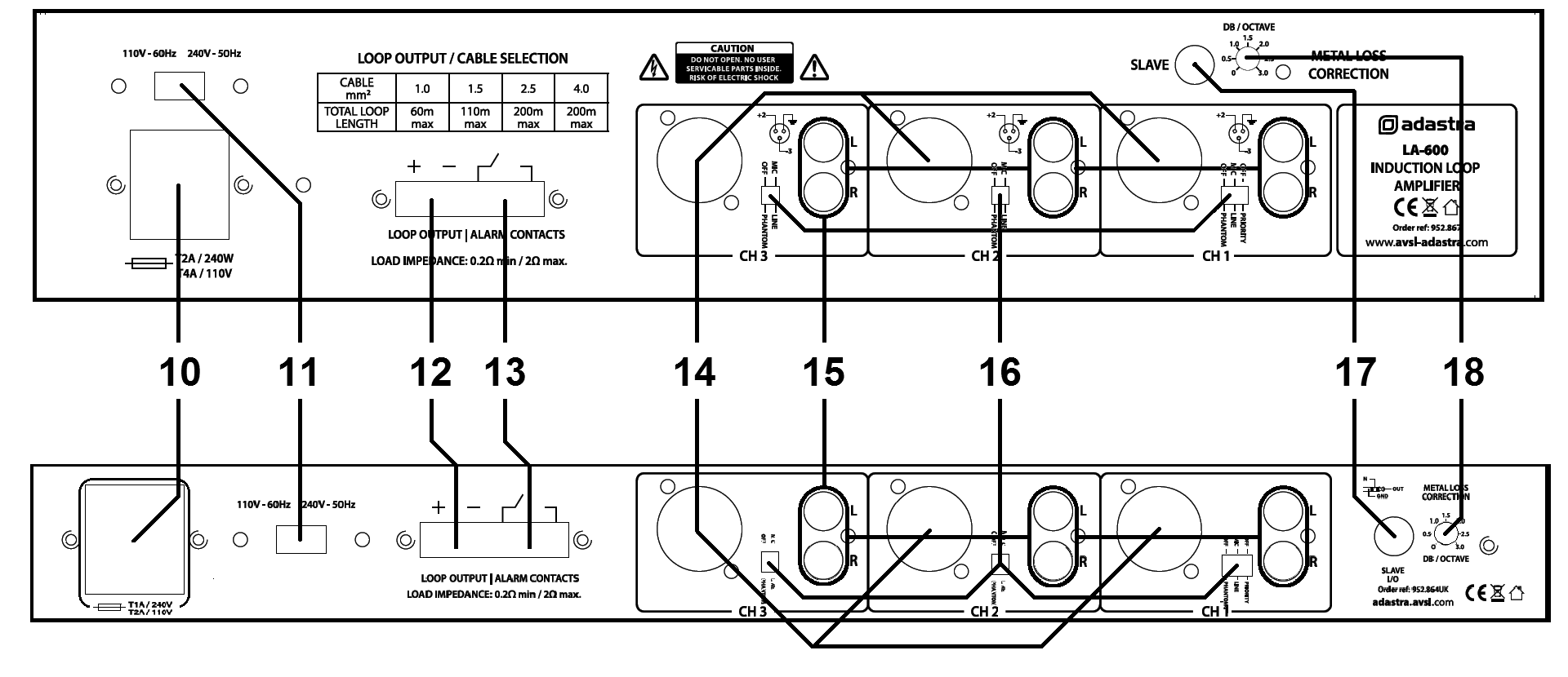
Rear panel
|
|
|
|
| 10. |
Mains voltage selector |
15. |
Unbalanced RCA inputs |
| 11. |
Combined IEC mains inlet and fuse holder |
16. |
Mic/line level, phantom & priority DIP switches |
| 12. |
Loop output terminals |
17. |
Combined Slave input/output |
| 13. |
Alarm contact terminals |
18. |
Metal loss correction adjustment |
| 14. |
Balanced combo jack/XLR inputs |
|
|
Installation
The LA series loop amplifiers can be operated free-standing or fitted
into a standard 19” rack cabinet using the supplied rack ears. Ensure
that the unit is positioned on a stable surface with adequate cooling
ventilation.
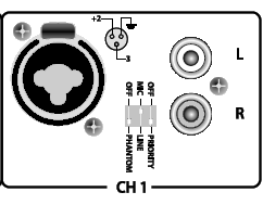
There are 3 input channels which can accept inputs via balanced XLR or
6.3mm jack connection (14) or unbalanced RCA connection(15).
The XLR/jack connectors can be set to accept microphone or line level
via the Mic/Line DIP switches (16), which are also accompanied by
switches for activating phantom power (+20V) for use with condenser
microphones.
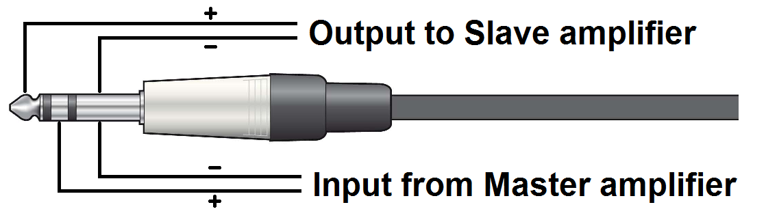
Multiple loop amplifiers can be used in master/slave mode using the
combined slave input/output jack (17). Connecting a stereo 6.3mm plug to
this socket gives 2 wiring options as shown below.
Connecting a mono 6.3mm plug will function as a slave output. A TRS plug
with signal connected to the ring will be needed for a slave input from
another loop amplifier.
Alarm contacts (13) are provided, which will emit a siren on the
induction loop when the connection is made.
These can be connected to an emergency switch or alarm panel contacts to
activate the siren for emergency evacuation, indicated by an LED on the
front panel (7)
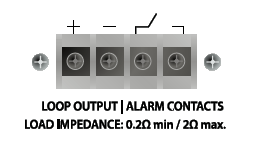
Alongside the alarm contacts are the screw terminals for the induction
loop (12). Connect the 2 ends of the loop wire to these terminals,
ensuring no stray strands or shorted connections. See below for details
about installing the loop wire before connecting mains power to the loop
amplifier.
Mains is connected via a rear panel IEC connector (11) with a built-in
mains fuse.
Use the supplied lead and ensure that the correct mains voltage is set
on the voltage selector (10).
Induction loop cable installation
Prior to installation, it is important to check if there will be any
equipment in the vicinity that may interfere with the loop’s magnetic
field, such as large transformers, high power cables or substations. It
is also important to ensure that no equipment will be adversely affected
by the loop field, such as sensitive data or signal cables. In these
cases, it may not be possible to cover some or any of the required area
with an induction loop.
The cable gauge will depend upon the total length of the induction loop.
Usually, the loop will be installed around the perimeter of the
listening area. However, there are various techniques which can be
employed to build arrays to vary the shape and strength of the field. In
general, calculations outlined here are based upon a perimeter
installation.
It is recommended to use good quality insulated pure copper cable for
the induction loop. The cable gauge used will need to be determined by
the total length of the cable run. The LA-series loop amplifiers are
designed to operate with a load of between 0.2Ω and 2Ω. The following
equation can be used to calculate the total cable resistance, which will
show if the gauge is correct.
R = Cable length (m) x 0.01786Ω*mm²/m (specific resistance of
Copper)
Cable CSA (mm²)
So, for a cable 80m long with a Cross-Sectional Area (CSA) of 1.5mm²… R
= 80/1.5 x 0.01786 = 0.9525Ω
So, this gauge of wire (1.5mm²) would be OK for the 80m run because it
is between 0.2Ω and 2Ω
As a quick reference, refer to the table below.
| Cable CSA (mm²) |
1.0 |
1.5 |
2.5 |
4.0 |
| Total Loop Length |
60m max. |
110m max. |
200m max. |
Over 200m |
The wire may be run in plastic conduit but not in any metal containment
so as not to impair the magnetic flux. The ideal height to install the
cable depends upon the width of the loop (i.e. the narrowest dimension
relative to the listener). The optimum output will be achieved if the
cable is installed 14% of the loop width higher or lower than the plane
of listening (ear height).
In practical terms, the loop is usually installed onto skirting boards,
under flooring or at ceiling height so that it is unobtrusive. It is
recommended to avoid varying height levels as much as possible to avoid
anomalies in field strength.
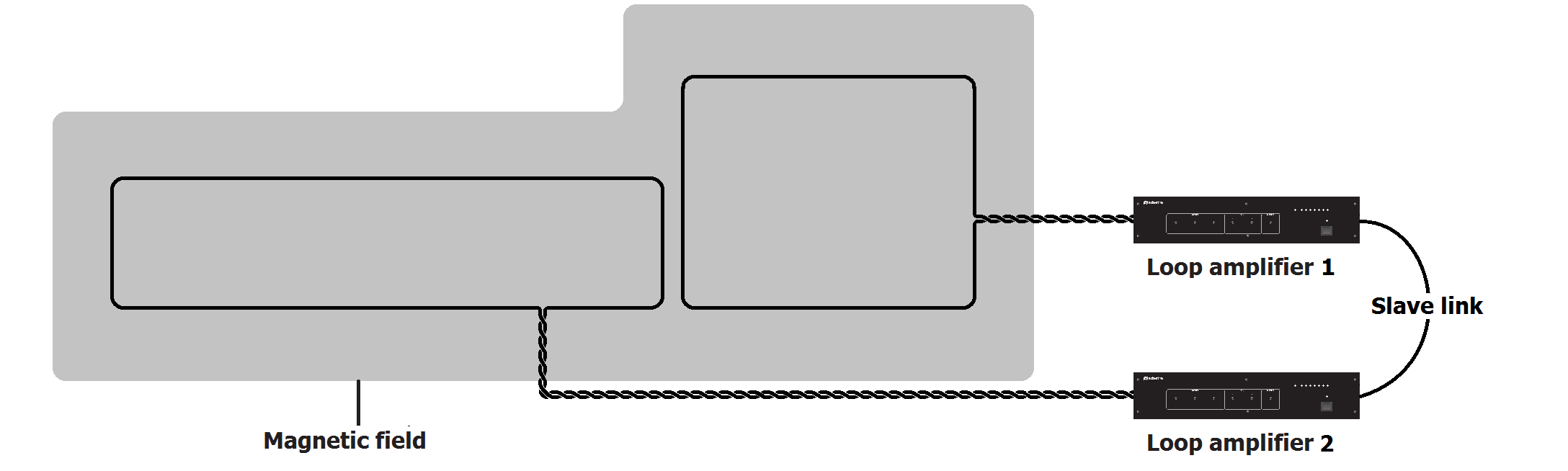
For irregular shaped areas or larger than the loop amplifier’s capacity,
multiple induction loops may be required for coverage. Connecting
further loop amplifiers using the Slave connection will enable multiple
loops to be used together.
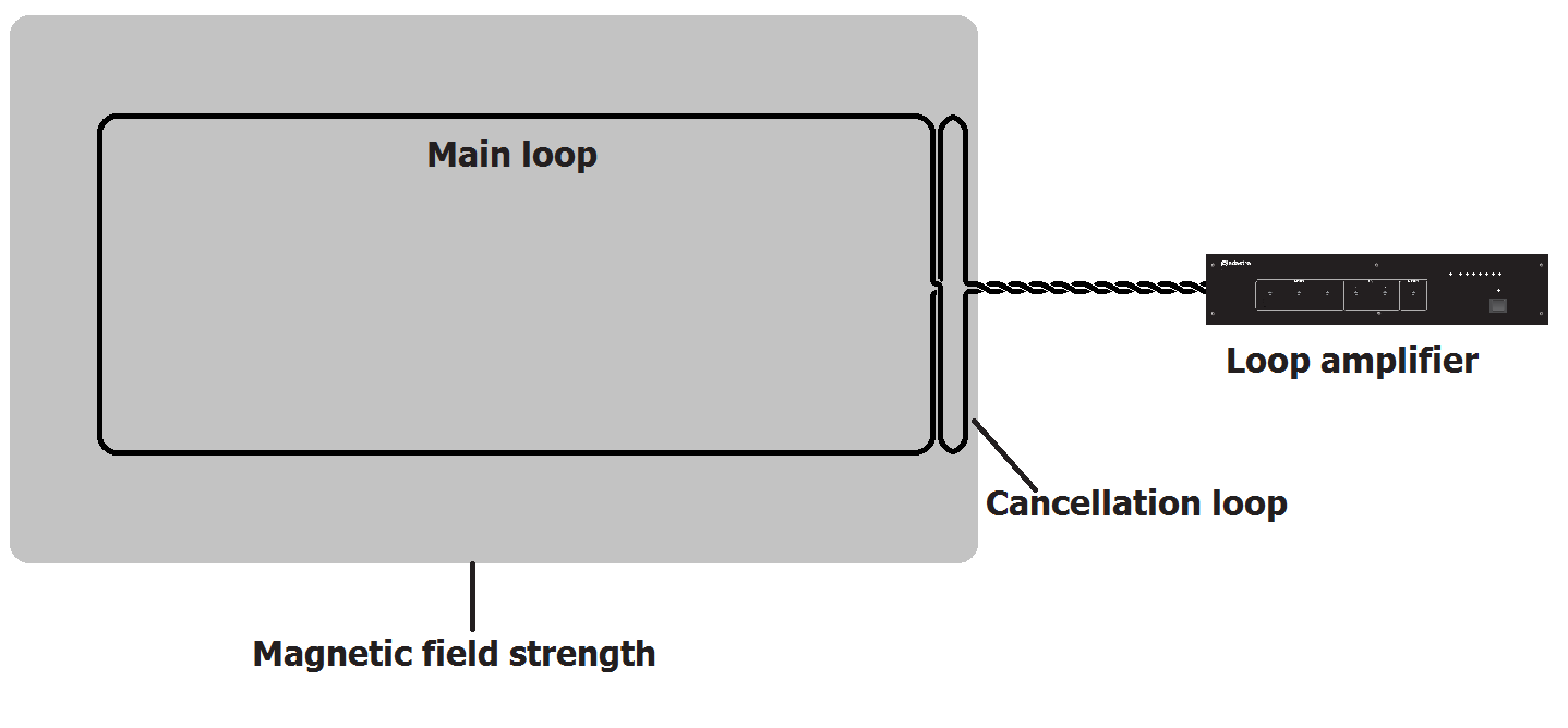
Cancellation Loops
If there are areas adjacent to the loop where the magnetic field would
cause problems, it is possible to avoid this by use of a “cancellation
loop”, which is a narrow loop parallel to the main loop at the problem
area.
This loop is the opposite polarity to the main loop and causes the
magnetic field to narrow along the adjacent edge of the main loop to
control the spill of the loop field.
Connection
Connect any line sources (e.g. CD player, mp3 player) or microphones to
one or more of the input channels.
If a microphone is connected, select “MIC” on the DIP switches and
connect via 6.3mm jack or XLR input.
If the microphone is a condenser microphone requiring phantom power,
select “PHANTOM”.
For standard dynamic and battery powered microphones, set the Phantom
switch to “OFF”
For line inputs, select “LINE” on the DIP switches.
For channel 1, there is an option for “PRIORITY” over the other two
channels, which will mute the output of channels 2 and 3 when there is
an input to channel 1.
If the loop amplifier is to be used in conjunction with a PA system with
loudspeakers, connect the line or aux output from the PA system to a
Line input on the loop amplifier via RCA, jack or XLR connection.
Ensure that this input is set to “LINE” and Phantom is set to “OFF”
Before connecting the induction loop to the amplifier, use a test meter
to check the D.C. resistance in the wire. Ensure that there are no
shorted or grounded points in the wire and that the total resistance is
not less than 0.2Ω
Twist the loop wires from where the loop ends to the amplifier terminals
to avoid creating an extended loop to the area where the amplifier is
situated.
With the power switched off (9), connect the loop cable to the loop
terminals (12) on the rear panel of the loop amplifier.
Operation
The front panel controls on the loop amplifier are recessed and can be
adjusted using a flat blade screwdriver. This is to avoid tampering or
mal-adjustment after the correct settings have been applied.
Where new or unsupervised operators are making adjustments to equipment
in the venue, they may not be aware if they have adjusted the induction
loop settings unless they themselves are a hearing aid user.
Set the Ch.1, Ch.2, Ch.3 and Loop Current controls (1, 2, 3, 6) to
minimum and keep the Bass and Treble controls (4, 5) in the mid position
(12 o’clock)
Power up the loop amplifier and increase the Loop Current control (6)
part way.
Whilst playing a signal into one of the input channels, gradually
increase the level (1, 2 or 3) until the peak current indicator (8)
shows movement.
The optimum operating level is achieved if the channel level controls
are set so that if all connected signals are at maximum level, the Peak
Current indicator does not show overloading.
It is recommended to use an induction loop receiver (952.855UK) to check
the audio from the induction loop.
Adjust the Loop Current control to set the main audio level from the
induction loop.
The Metal Loss Correction control (18) enhances higher audio frequencies
which may be absorbed by metal architectural features and appliances
within the induction loop area. If the building has a lot of metal
structure or reinforced concrete in the vicinity of the loop, use this
control to adjust the audio quality of the loop signal.
Adjust Bass and Treble controls (4, 5) to set the tonal characteristics
of the audio from the induction loop.
The mid-point (12 o’clock) is the zero position. Turning to the left of
the mid-point will cut Bass or Treble and to the right of the mid-point
will boost Bass or Treble.
When the induction loop is not required, ensure that no hearing aid
users are remaining within the loop area and switch off the loop
amplifier (leaving the settings in position will ensure that the
induction loop is set up correctly for the next usage).
