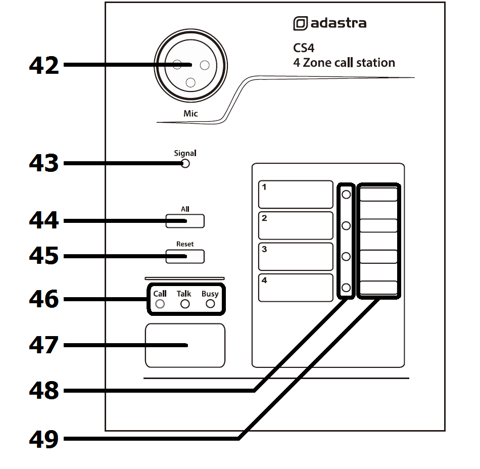
CS4 Call Station
| No | Function |
|---|
| 42. | XLR paging microphone connection |
| 43. | Call station signal indicator |
| 44. | Select ALL zones for paging |
| 45. | Reset zones to BGM (background music) |
| 46. | Call status indicators |
| 47. | Page button |
| 48. | Zone selection indicators |
| 49. | Zone select buttons |
| No | Function |
|---|
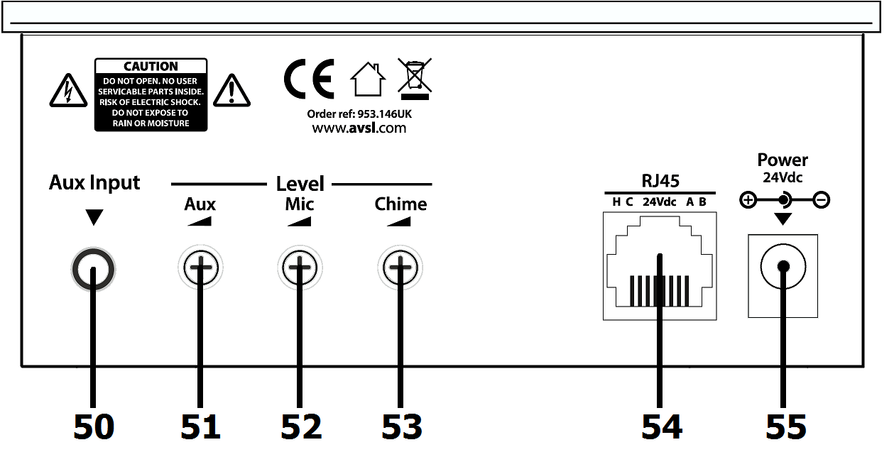
| 50. | Aux line input 3.5mm stereo jack |
| 51. | Aux level control |
| 52. | Paging mic level control |
| 53. | Chime level control |
| 54. | RJ45 connector (to RM244V) |
| 55. | 24Vdc power input (>100m cable run) |
CS4 Operation
Select which zones are to be paged using the Zone Select buttons (49) or All Zones button (44)
Zone Select indicators (48) will light for the zones that are “armed”.
Pressing the Reset button (45) removes all zone selections.
When one or more zones are armed, pressing the Page button (47) will mute the media player (background music) to all zones and activate the chime (if a chime setting is selected – see below)
The CS4 microphone will be activated and any speech/audio will cause the Signal LED (43) to light.
Announcements into the CS4 microphone will be heard in the selected zones only.
Pressing the Page button again will deactivate the microphone and all zones will be reset back to BGM after a few seconds.
Chime Function
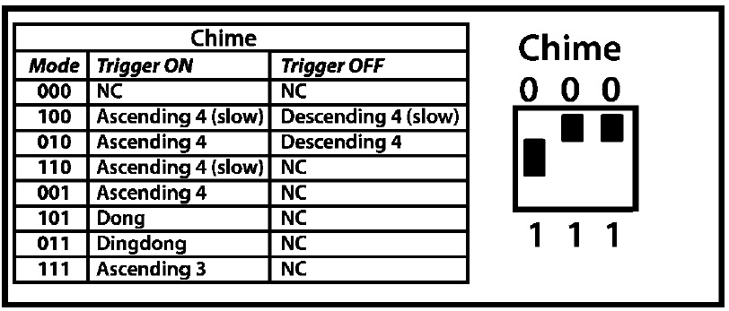
The CS4 has a programmable chime function, which is set by DIP switches on the side of the base unit. The chart printed next to the DIP switches shows the chime setting variations.
The Chime level and Microphone level are adjusted via miniature rotary controls (52,53) on the rear of the CS4 base unit. Next to these is a level control (51) for a local Aux input, which allows connection of a stereo line input (e.g. smart phone or laptop) to a 3.5mm jack on the left side (50).
