The Adastra RM244V rackmount 100V amplifier is a 4 output mixer-amp with
built-in media player + Bluetooth® and individual level and mute control
for each output. Up to 2 CS4 call stations can be used with the RM244V
to create a flexible 4-zone paging system.
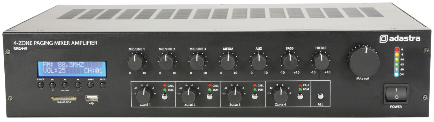
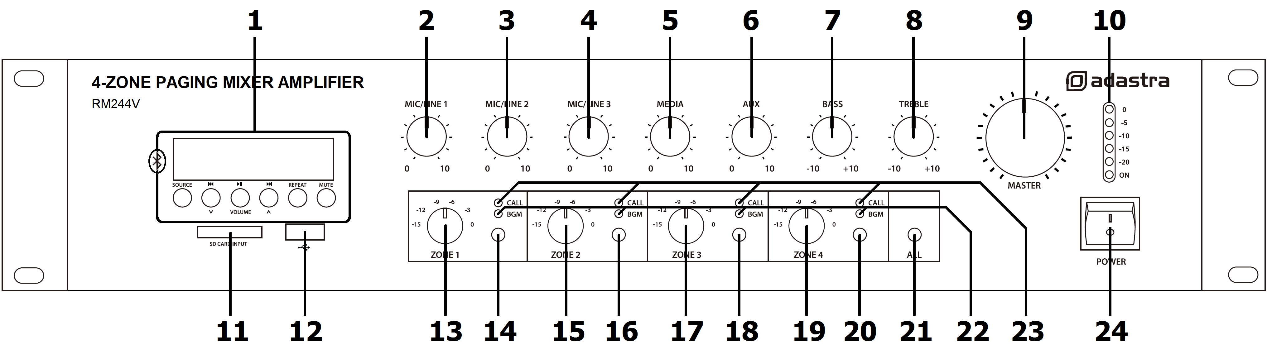
Front Panel
|
|
|
|
| 1. |
Media player section USB/SD/FM/BT |
13. |
ZONE 1 volume attenuator |
| 2. |
MIC/LINE 1 volume control |
14. |
ZONE 1 call select |
| 3. |
MIC/LINE 2 volume control |
15. |
ZONE 2 volume attenuator |
| 4. |
MIC/LINE 3 volume control |
16. |
ZONE 2 call select |
| 5. |
MEDIA player volume control |
17. |
ZONE 3 volume attenuator |
| 6. |
AUX line in volume control |
18. |
ZONE 3 call select |
| 7. |
BASS EQ control |
19. |
ZONE 4 volume attenuator |
| 8. |
TREBLE EQ control |
20. |
ZONE 4 call select |
| 9. |
MASTER volume control |
21. |
ALL outputs page select |
| 10. |
VU meter LEDs |
22. |
BGM background music (media) indicator |
| 11. |
SD card slot |
23. |
CALL paging indicator |
| 12. |
USB media port |
24. |
POWER switch |
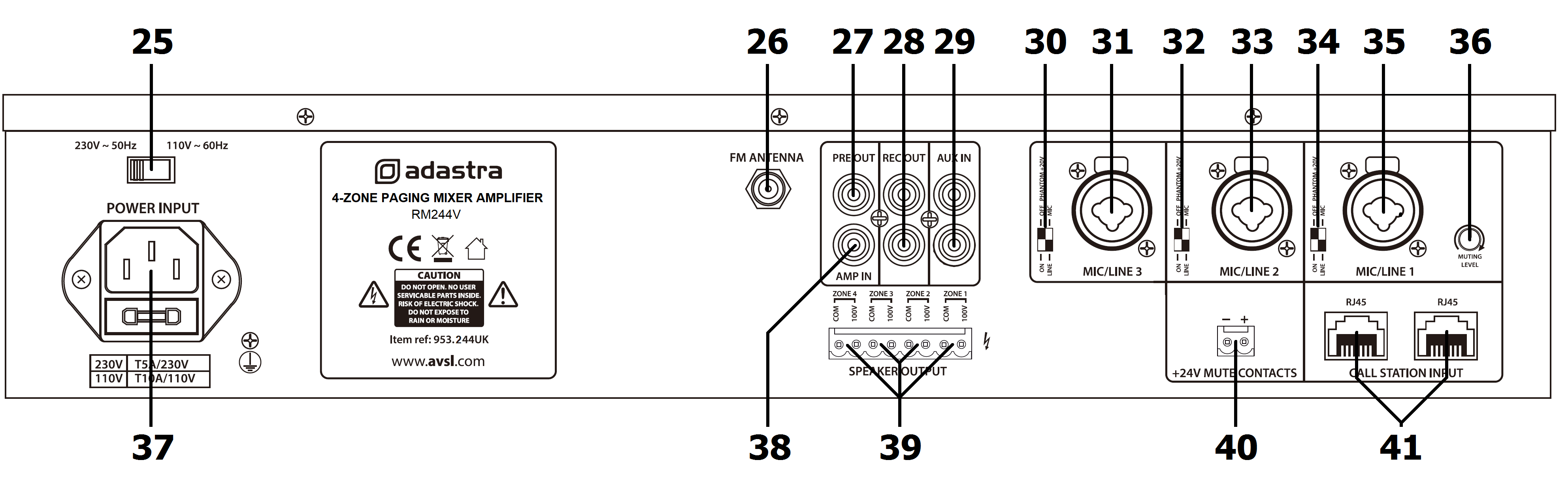
Rear Panel
|
|
|
|
| 25. |
Voltage select |
34. |
Channel 1 MIC/LINE + PHANTOM switches |
| 26. |
FM ANTENNA ‘F’ connector |
35. |
Channel 1 input XLR/jack |
| 27. |
PRE OUT (loop send) RCA |
36. |
Channel 1 priority MUTING LEVEL |
| 28. |
REC OUT recording output 2 x RCA |
37. |
Mains power inlet IEC and fuse holder |
| 29. |
AUX IN line input 2 x RCA |
38. |
AMP IN (loop return) RCA |
| 30. |
Channel 3 MIC/LINE + PHANTOM switches |
39. |
SPEAKER OUTPUT modular screw terminals |
| 31. |
Channel 3 input XLR/jack |
40. |
24V MUTE modular screw terminals |
| 32. |
Channel 2 MIC/LINE + PHANTOM switches |
41. |
CS4 CALL STATION connectors 2 x RJ45 |
| 33. |
Channel 2 input XLR/jack |
|
|
Connection and Setup
Connect the rear IEC inlet (37) to the mains supply using the IEC power
lead provided (or an equivalent approved type). Ensure that the voltage
is correct as indicated on the voltage selector (25) and that the mains
outlet is switched on.
The RM244V has 3 mic/line inputs which can accept XLR or 6.3mm
balanced/unbalanced connection. There is also an Aux line input via 2 x
RCA on the rear panel and up to two CS4 call stations may be connected
via RJ45 on the rear panel.
DIP Switches
Mic/Line inputs each have 2 DIP switches (30, 32, 34) which should be
set for the input type.
 The left DIP switch selects whether +20V phantom
power is supplied to the XLR input for condenser microphones or paging
microphones with built-in chimes. This should be switched to the down
position if phantom power is required.
The left DIP switch selects whether +20V phantom
power is supplied to the XLR input for condenser microphones or paging
microphones with built-in chimes. This should be switched to the down
position if phantom power is required.
The right DIP switch selects the input level for XLR or 6.3mm jack. This
should be switch to the up position for microphones or the down position
for line level inputs to match the input level correctly and avoid
overloading the channel.
Be sure to make these DIP switch settings when the amplifier is switched
off and prior to connecting inputs to the RM244V. Making any changes
when the amplifier is powered up may cause loud bangs through the system
which can damage the speakers.
Mic/Line 1 input also has a priority function, which can reduce the
output of the other channels (Mic/Line 2 & 3, Aux and Media) when MIC 1
signal is detected and returns them to normal when MIC 1 signal is
silent.
The amount by which this “override” mutes the other channels is set by
adjusting the MUTING LEVEL control (36). Turning this control clockwise
increases the muting effect on the other channels and turning
anti-clockwise reduces the muting effect.
The priority function for Mic/Line 1 does not affect any CS4 call
stations connected to the RM244V.
With the power switched off, connect microphones or mono line inputs to
Mic/Line inputs 1, 2 and 3 using good quality XLR or 6.3mm jack leads.
Connect any other line level audio inputs to the AUX IN (29) connectors
on the rear panel using a good quality RCA lead. Since the amplifier has
a mono output, stereo signals will be summed together.
Further mixer-amplifiers, slave amplifiers or recording devices can be
connected to the rear REC OUT (recording output) sockets, again using a
good quality RCA lead. This output carries the full mix of all channels
(including the internal media player) but is not affected by the MASTER
volume control.
The RM244V also has RCA connectors for PRE OUT and AMP IN, which can be
used as Send and Return in a series loop for connecting audio processors
or as Mix output and Slave input separately.
Speaker Outputs
The RM244V has 4 separate outputs for connecting 100V line speakers.
These are arranged on a single modular connector for convenience. Each
output has 2 screw terminal connections.
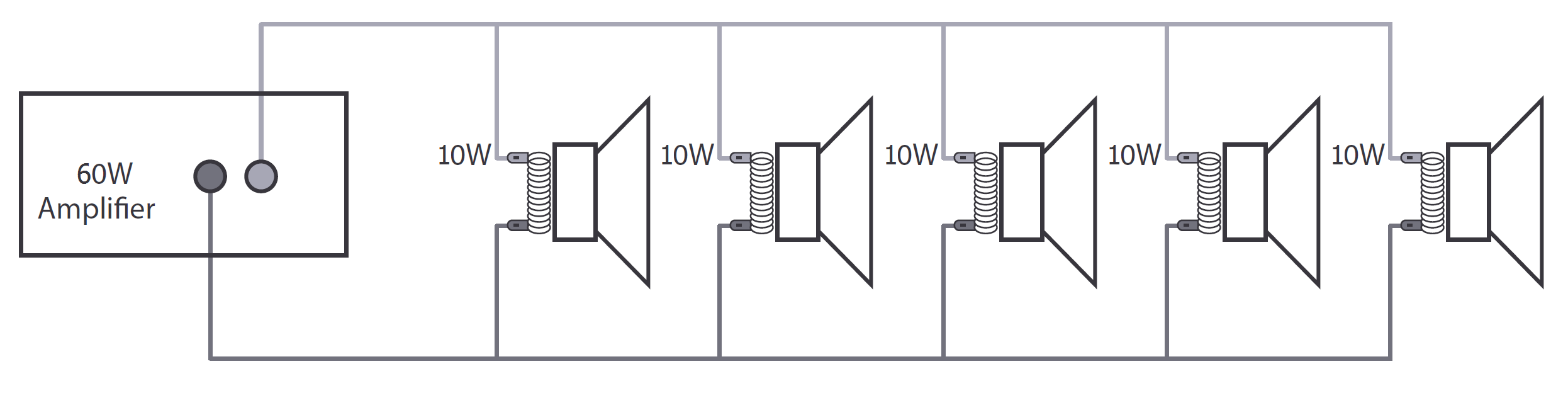
For each zone output, connect the “100V” output terminal to the positive
(+) connection of the speaker and “COM” output to the negative (-)
connection of the speaker. Connect further speakers in parallel to the
first speaker with all positive terminals and connected together and all
negative terminals connected together as shown below.
Repeat this process for all 4 zone outputs as required. Usually, each
zone represents a specific room or area and connecting these separately
will allow individual control and paging for each zone.
A 100V line speaker system can comprise of many speakers connected
together. The determining factor for how many speakers can be used on a
single amplifier is the power rating. For most purposes, it is advised
to connect as many speakers as needed with a combined wattage of no more
than 90% of the amplifier’s output power rating.
In the case of the RM244V, the maximum power output is 240W, shared
across all 4 zones. This means that a recommended maximum 216W
combination of speakers can be connected to a single zone or shared
across all 4 zones (so long as the total does not exceed 216W)
Emergency 24V Contacts
For fire alarm panels with 24V trigger out, connect to the trigger to
the 24V contacts on the RM244V.
When the fire alarm is activated, 24V trigger on these terminals will
mute all except CS4 call stations.
(The 24V contacts can be connected with either polarity +/- or -/+ to
operate)
Connecting a CS4 Call Station
The CS4 call station is a bespoke optional addition to the RM244V system
and up to 2 of these can be connected to a single amplifier by RJ45 with
CAT5 network cable. This is not a standard LAN connection and should
only be connected directly to the RM244V.
The CS4 call station comprises a base unit and paging microphone.
Connect the microphone to the XLR input on top of the base unit.
Connect the RJ45 connector on the rear panel of the CS4 to one of the
RJ45 inputs on the rear of the RM244V. The CAT5 cable carries power to
the CS4 and control and audio signals to the RM244V.
If the CAT5 cable run is further than 100m, it will be necessary to
connect 24Vdc power to the DC jack of the CS4 for operation up to 1000m
cable length.
Operation
When all connections to the RM244V are made, turn all rotary controls
down and switch on the power (24) and a power “ON” LED will illuminate.
Turn BASS and TREBLE EQ controls (7, 8) to the 12 o’clock position
(pointing straight up) and turn the MASTER control (9) up part way for
testing.
Press the ALL button (21) to engage all speaker outputs (the green BGM
LEDs should be lit)
Ensure a signal is being fed to one of the Mic/Line 1, 2, 3 inputs or
Aux and gradually increase the volume control for that channel until the
output is heard through the speakers. Turn up the MASTER to the maximum
required volume level and reduce the channel volume control if
necessary.
Repeat this process for any other microphones or line inputs connected
to the RM244V.
Note: If a line input is not connected to the RM244V, the initial test
can be made using the built-in media player from USB/SD, FM tuner or
Bluetooth. See section below for instructions.
The output of the amplifier is represented on the VU meter LEDs (10) and
care should be taken that the Red “0” LED is only lit momentarily during
use. Anything longer than a short flash of this LED may be indicating
distortion or clipping of the output signal and the MASTER should be
turned down.
If a microphone is connected to MIC 1 input, make sure it is switched on
and if it requires phantom power, make sure this feature is enabled.
Gradually increase the MIC 1 control (2) whilst speaking into the
microphone until the required volume level is reached. The microphone
should not be able to “hear” the speakers, which can cause feedback
(squealing or howling noise).
Repeat this process for microphones connected via the MIC/LINE 2 and
MIC/LINE 3 inputs.
In addition to channel and MASTER volume controls, there are BASS and
TREBLE EQ controls to adjust the tone of the overall output. At the 12
o’clock position, these controls are applying no effect to the signal
(no boost or cut).
Moving the BASS control clockwise boosts the low frequencies in the
audio, whilst moving it anticlockwise will cut these low frequencies.
Likewise, moving the TREBLE control clockwise boosts the high
frequencies in the audio, whilst moving it anticlockwise will cut these
high frequencies.
Adjust these EQ controls to suit the type of audio signal or compensate
for the room acoustics.
Zone Outputs
The RM244V has 100V speaker output connections for 4 separate zones,
which are governed by 4 rotary switches on the front panel (13, 15, 17,
19). Although the RM244V has a single amplifier, its output is shared
across 4 volume attenuators, which are adjusted by these rotary
switches, giving an independent level control for each zone (the sound
source for all 4 zones will always be the same).
Furthermore, each zone output is controlled by a select button (14, 16,
18, 20), which selects a zone to BGM (background music) or CALL (mute
unless paged from CS4) with LED indicators to show its status. If no CS4
call stations are connected, these act as mute buttons for each zone.
The ALL button (21) operates as a select button for all zones
simultaneously.
Turn down the volume controls when powering down the RM244V to avoid
damage to the speakers.
Media Player
The RM244V is fitted with a built-in media player, which allows playback
of music or audio messages stored as standard compressed audio files on
either USB pen drive or SD card.
The media player also has an FM radio tuner function and Bluetooth
receiver as described below.
The output level of the media player is controlled by the MEDIA control
(5) on the front panel.
Controls
| SOURCE |
USB / SD / FM tuner / Bluetooth input source selector |
|
Previous track or FM channel / volume down |
|
Play or pause current track / auto tune FM stations |
|
Next track or FM channel / volume up |
| REPEAT |
Repeat mode – off, single track or all |
| MUTE |
Mute media player output |
USB/SD
Push a USB pen drive into the USB port (12) and/or SD card into the SD
card input (11) and the audio files will start to play automatically.
Turn up the MEDIA control gradually to hear the output from the speakers
and increase to the required level.
If play does not start automatically, press the SOURCE button and
Play/Pause button () to check if the player is set to play from the
required memory device. If playback still does not start, try pressing
the Previous track and Next track buttons (, ). Otherwise, check that
the audio files are standard compressed type.
Normal playback will read through all tracks on the storage device.
Pressing the REPEAT button (7) will step through the repeat modes.
RT1 = repeat current track
RND = random play
RTA = repeat all tracks
Pressing the Previous track button () briefly steps backwards through
tracks on the memory device. Press and hold this button to decrease the
playback volume.
Pressing the Next track button () briefly steps forwards through tracks
on the memory device.
Press and hold this button to increase the playback volume.
To pause the current track, press the Play/Pause button () and press
again to resume playback.
The LCD display will show the track number when a track is selected and
then the elapsed time when it is playing.
FM Tuner
The FM tuner function operates in the same way as a standard FM radio
and benefits from the connection of an FM antenna to the rear panel ‘F’
type connector (26).
If no channels are tuned in, press the Play/Pause button () to begin
auto tuning, which scans available stations and stores them as channels
within the FM tuner.
Pressing Play/Pause again will abort the auto-tuning.
To step through pre-set stations, press the Previous or Next (, )
buttons.
Holding the Previous track or Next track buttons will adjust the output
volume of the player.
Bluetooth
The Bluetooth function allows connection of a smart phone or tablet to
the media player section for playback of stored files or streamed
digital audio.
In order to enable this function, it will be necessary to pair the
sending device to the receiver as follows.
Open the Bluetooth settings menu on the smart phone or tablet (or
other sending device)
Scan for Bluetooth devices and look for “adastra 0000” in the list
of available devices
(ensure that the RM amp is powered on and within reception range)
Select “adastra 0000” and the sending device should confirm that it
is connected as an audio device. (note that “0000” may be a
different number if it has been edited – see below)
Play audio from the sending device, ensuring that volume controls
are not turned down/muted
Turn up the LN5/USB volume control on the amplifier to the required
level.
The Previous, Next and Play/pause buttons will operate in Bluetooth as
remote playback controls. Holding the Previous track or Next track
buttons (2, 5) will adjust the output volume of the player.
The Bluetooth name can be customized to enable identification of
individual nearby amplifiers.
To customize the Bluetooth number press and hold the Play/Pause button
until adastra 0000 is displayed with one of the characters flashing.
Press Previous or Next buttons to edit the number and Play/Pause to
select another character.
Hold Play/Pause to store the ID and exit.
Note: Android devices have the facility to re-name devices within the
Bluetooth settings menu.
If a the Bluetooth ID has been re-named on the Android device, editing
the Bluetooth ID on the media player will not affect the name displayed
on that Android device.
Track navigation can be controlled from the paired device or from the
front panel of the RM244V.
Previous, Next and Play/pause buttons (, , ) will operate in Bluetooth
as remote playback controls.
Holding down the Previous or Next buttons will also adjust the volume of
the player.
