UA30 Compact 100V Mixer-Amplifier
Thank you for choosing an Adastra UA30 mixer-amplifier as part of
your public address system.
This unit is designed to offer high quality, dependable service for
mobile and installed systems.
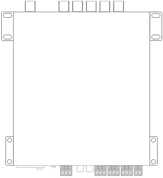
Rack Mounting
The UA series amplifiers can be mounted into a 19” rack cabinet using
the supplied rack accessories.
As shown below, the 2 joining brackets link a pair of UM series
amplifiers together to form a full-width 1U rack-mount pair. One rack
ear can be mounted at each end for fixing to the rack strip.

Wall or under counter mounting
The rack mounting accessories can also be attached so that the amplifier
can be mounted against a wall or under a counter or work surface. To do
this, mount the rack ears with the tabs aligned with the top of the
housing to provide mounting holes to screw the amplifier to the
underside of a work surface or against a wall with the controls visible
vertically.
Front Panel
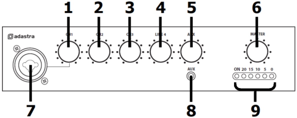
1. CH1 volume control
2. CH2 volume control
3. CH3 volume control
4. LINE 4 volume control
5. AUX volume control
6. MASTER volume control
7. CH1 XLR/Jack input
8. 3.5mm stereo AUX input
9. Power and Audio output indicators
Rear Panel
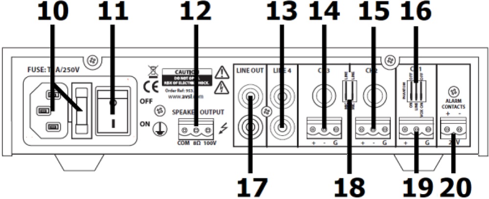
10. IEC power inlet and fuse holder
11. Power on/off switch
12. 100V and 8Ω speaker output terminals
13. LINE 4 RCA input
14. CH3 6.3mm and screw terminals input
15. CH2 6.3mm and screw terminals input
16. CH1 Phantom-Mic/Line-Vox DIP switches
17. LINE OUT RCA output
18. CH2/CH3 Mic/Line DIP switches
19. CH1 screw terminals input
20. 24V MUTE terminals
Connection and Setup
Set the rear power switch (11) to the “off” position and connect the
rear IEC inlet (10) to the mains using the supplied mains lead (or an
equivalent approved type). Check that the supply voltage is 170-264Vac
50Hz.
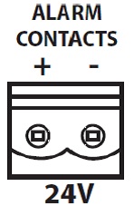
A pair of screw terminals is provided on the right side of the rear
panel for connection to an alarm system if required (20). This
connection will mute all channels except CH.1 (for alerts) when 24V is
present across the terminals. (24V is a standard trigger voltage from
most fire and security panels).
Note: Screw terminal blocks can be unplugged from the panel for
convenience during connection.
If using a main microphone for paging or announcements, connect this to
the CH.1 input on the front panel (7) via either XLR or 6.3mm jack. This
may also be a line level (such as CD or mp3) input if required.
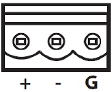
Alternatively, the CH.1 mic or line source can be connected on the rear
panel via a screw terminal input (19), which is labelled “+ / - / G”.
For Unbalanced connection, connect the signal (core) wire to “+” and
connect the Ground (braid) to “- and G”.
For Balanced connection, there will be 2 core wires. Connect the hot
(usually red) wire to “+” and the cold (white, black or blue) wire to
“-”. Then connect the Ground (braid) separately to “G”.
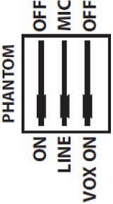 CH.1 has a bank of 3 DIP switches dedicated to it
on the rear panel (16) above the terminals.
CH.1 has a bank of 3 DIP switches dedicated to it
on the rear panel (16) above the terminals.
The right-side DIP switch allows the VOX function to be switched on or
off.
When this function is switched on, the input to CH.1 will override the
other inputs, causing the volume of any of the other 3 channels to be
suppressed when any sound is present on CH.1
When CH.1 is silent, the other 3 channels return to full output volume
automatically.
This function is useful for “auto-ducking” background music when making
announcements.
The centre of the 3 DIP switches selects between MIC or LINE input.
Position this switch depending upon which input source is used, so that
the correct channel input level is set for the input type.
The left side DIP switch is labelled “PHANTOM” and switches 24Vdc
phantom power to the CH.1 front XLR input for use with paging or
condenser microphones that require phantom power.
CH.2 and CH.3 can also accept either microphone or line input, via
either 6.3mm jack or screw terminal inputs on the rear panel (14, 15)
The screw terminals for CH.2 and CH.3 are connected in the same way as
described above for CH.1
For 6.3mm jack, connection can be Unbalanced (Tip +, Sleeve -/GND) or
Balanced (Tip +, Ring -, Sleeve GND)
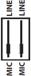 There are a pair of DIP switches (18) for CH.2 and
CH.3 to select MIC or LINE, depending upon the input type. Note: No
phantom power or vox override are available on these inputs.
There are a pair of DIP switches (18) for CH.2 and
CH.3 to select MIC or LINE, depending upon the input type. Note: No
phantom power or vox override are available on these inputs.
CH.4 is an input for Line level only and is connected via a pair of RCA
sockets (13)
Connect the Left and Right output from a CD, mp3, DAB/FM tuner, message
machine or other line level source to these sockets using a standard
twin RCA/phono lead (L+R are summed to mono).
CH.5 is an auxiliary input connected via a 3.5mm stereo jack on the
front panel (8).
This is a line input and can be used for connecting a smart phone,
laptop or mp3 player for audio playback.
A twin RCA line output (17) is provided for connecting the mix of all
channels onto further amplifiers.
Speaker Connections
The UA series amplifiers can be used either as 100V line amplifiers or
standard low impedance power amplifiers. These 2 configurations cannot
be used together, so it is important to decide which method will be used
at the start.
Operation
When all connections to the amplifier are made, turn all rotary controls
down and switch on the power (11)
A power LED will illuminate at the left side of the audio output
indicator LEDs (9).
Use either a microphone or a line input signal for checking the system.
Turn up the MASTER rotary control (6) part way for testing and increase
the rotary control for the channel being used for testing (1-5) until
the output is heard through the speakers. Turn up the MASTER to the
maximum required volume level and reduce the channel volume control if
necessary. Then check each input being used in turn to set the correct
level.
Note: If a microphone is being used, point it away from the speakers,
making sure that it is not able to “hear” the speakers, which can cause
feedback (squealing or howling noise).
When not being used, turn down the MASTER control before powering down
to avoid loud clicks or pops.
