CSX-18 Series Live Mixing Console
CSX-18 mixing console has been developed to provide
comprehensive range of audio requirements with high quality, reliable
results. Please read and keep this manual to achieve the best results
from your purchase and avoid damage through misuse.
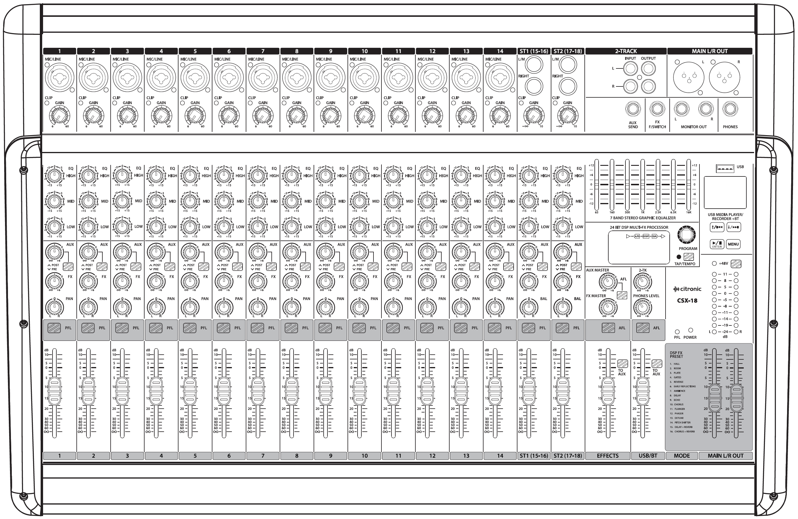
Console Layout
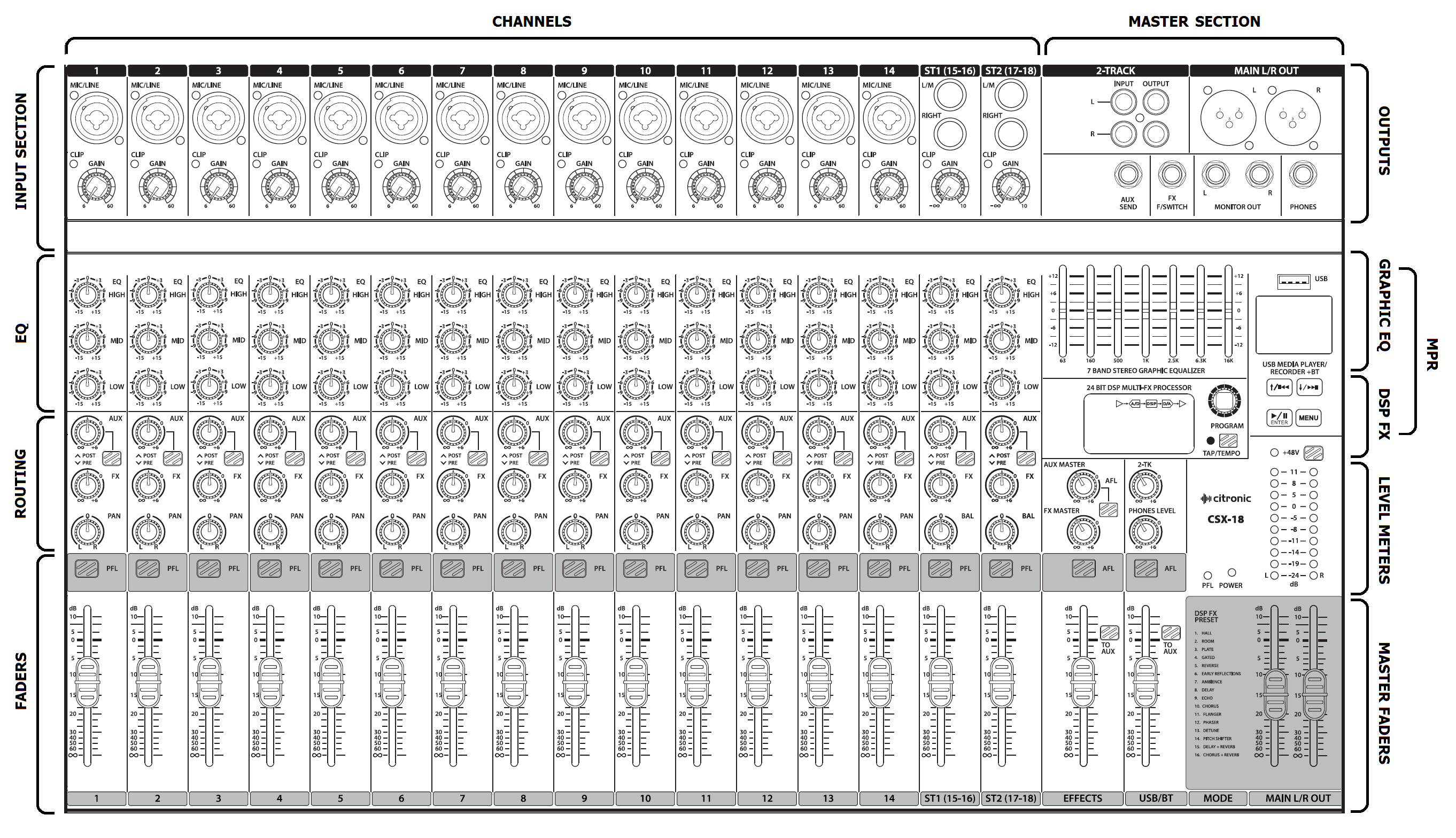
The CSX-18 has comprehensive input and output sections which can be
split further into various stages of processing and routing. All preamps
have studio grade, low noise architecture for the cleanest possible path
throughout the signal chain.
The input stages are repeated across each channel of the console, which
simplifies operation and enables quick and easy location of various
controls. The following pages of this manual are divided up into these
stages to explain the details and function of each control.
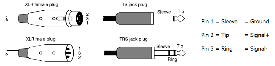
Mic/Line Input Connections
Channel inputs are provided as XLR and/or 6.3mm jack sockets.
The connections for these inputs are assigned as follows.
Channel Functions
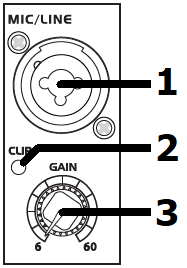
- MIC / Line input Connect a balanced microphone
or line input to this XLRF input.
An unbalanced microphone or line signal can be connected by XLR
provided that +48V phantom power is not used. Wired as follows.
| Balanced |
Pin 1 = Ground |
Pin 2 = Signal + |
Pin 3 = Signal – |
| Unbalanced |
Pin 1 = Ground |
Pin 2 = Signal + |
Pin 3 = Ground |
The Mic/Line input can also accept a 6.3mm balanced TRS or unbalanced
TS plug (jack plug). Phantom power does not affect
this connection. Wired as follows.
| Balanced |
Tip = Signal + |
Ring = Signal – |
Sleeve = Ground |
| Unbalanced |
Tip = Signal + |
Ring = Ground |
Sleeve = Ground |
2. Clip LED The CLIP LED lights when the channel is being overloaded.
Ideally, the Gain rotary control (described below) should be adjusted
so that the loudest passages of the input signal (e.g. bass drum
beats) will just momentarily trigger the CLIP LED. Anything longer
than a momentary flicker of the CLIP LED means that the Gain should be
reduced. Using the PFL button further down the channel strip gives a
more detailed view of the channel level on the main VU LEDs.
3. GAIN control This control trims the input signal to the optimum
level for the channel strip circuitry.
Too low a signal level can result in a weak signal-to-noise ratio and
too high can result in overload and distortion in the signal output.
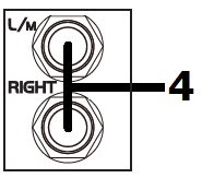
4. Stereo inputs The two right-most input channels on the console are
stereo with
Left and Right 6.3mm jack inputs. Alternatively, a mono signal can be
connected to the Left input jack and the channel will effectively
operate as a mono channel.
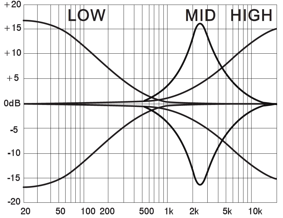
EQ Section

5. HIGH This control can boost or cut the high frequencies (centre 12kHz) by ±15dB (12 o’clock position is zero)
6. MID This control can boost or cut the mid frequencies (centre
2.5kHz) by ±15dB (12 o’clock position is zero)
7. LOW This control can boost or cut the low frequencies (centre 80Hz) by ±15dB (12 o’clock position isero)
Channel Routing
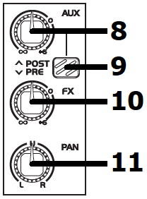
8. AUX This control governs the amount of signal from the channel
routed to the AUX SEND or auxiliary output to external equipment.
9.POST / PRE Pressing this button in changes the AUX output from POST
to PRE. POST is post-fader, meaning the signals to the AUX output are also affected by the channel fader level. PRE is pre-fader, meaning the signals to the AUX output are not affected by the channel fader level.
10. FX This control governs the amount of signal from the channel routed
to the effects section
11. PAN/BAL This control adjusts the amount of signal from the channel
fed to Left or Right outputs.
This varies the point in the stereo field that the signal appears. For
ST1 and ST2 channels, the PAN control is replaced with a BAL control
for Left/Right balance.
 Channel Faders
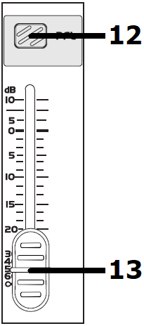
12. PFL Pre-Fade Listen sends the channel signal direct to monitoring. This means that the channel signal is shown on the main VU LEDs and routed directly to the headphones output. If many PFLs or AFLs are selected, all are routed to monitoring.
13. Channel fader 60mm fader to adjust the channel level to the master
output.
Output Section
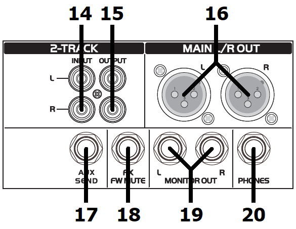
14. 2-TRACK INPUT L+R RCA line input shared with MPR
15. 2-TRACK OUT L+R RCA line output for recording or Monitoring
(pre-master-fader)
 MAIN L/R OUT L+R
16.MAIN L/R OUT L+R balanced XLR main outputs
17. AUX SEND 6.3mm jack mix of all channel AUX feeds
18. FX MUTE Connect a non-latching footswitch to this 6.3mm jack to mute/unmute the output of the DSP effects when pressed.
19. MONITOR OUT L+R 6.3mm jack outputs for monitoring. Volume is controlled by PHONES LEVEL.
20. PHONES Stereo 6.3mm jack headphones output. Volume is controlled by PHONES LEVEL.
Graphic Equalizer
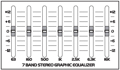
The main EQ is a stereo 7-band graphic equalizer to give overall tone shaping and can be used to help avoid feedback in live microphone setups.
Each slider controls a boost or cut of up to 12dB centred at the
specified frequency. Running from bass to treble, these are 63Hz, 160Hz, 500Hz, 1kHz, 2.5kHz, 6.3kHz and 16kHz
USB Media Player/Recorder
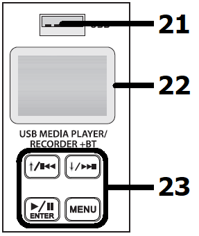
21. USB USB type A socket for connecting a USB stick or pen drive
22. Display Backlit LCD display showing playback or BT status
23. Controls Menu and navigation controls for media player/recorder
Main Menu
To step through the player options, press the MENU button. Use the and
buttons to navigate options: BT (Bluetooth), MSC (Music), REC (Record),
PC and SYS (System).
(PC is not currently functional on the CSX mixers – this is for future
development)
BT - Bluetooth Mode
To connect a smart phone or tablet to the CSX mixer via Bluetooth,
firstly make sure no USB device is connected (USB takes priority over
Bluetooth) and press the MENU button. Use the and buttons to navigate to
BT (Bluetooth) and press/to select. The display (22) will show Bluetooth
mode.
Enable Bluetooth on the sending device and select to pair with a device
called “Citronic”.
Once paired and connected, the display will state “BLUETOOTH CONNECT”
and “BT PAUSE” if a track is stopped or “BT PLAY” if a track is playing.
The transport buttons /, and will control tracks on the sending device
as they would for a USB track.
MSC - USB Playback
If no USB device is inserted, the display will state “NO DEVICE”
To initiate playback of audio files from a USB pen drive, insert the pen
drive into the USB port (21).
Playback should start automatically. If not, press the / button or
remove the USB drive and check that the files stored are either .mp3,
.wma, .ape or .flac format before re-inserting the drive. During
playback, the display will show the file name, elapsed time, playback
mode and track number.
To navigate through the tracks stored on the device, press the Previous
and Next buttons.
Press and hold the Previous or Next button to decrease or increase the
media player volume.
Press the Play/Pause button / to temporarily stop or resume the current
track.
Press the MENU button to see playback options for USB and use and
buttons to select an option.
Play Mode: Select All Play, One Device, One Play or Random and press /
to confirm.
- All Play will play through all tracks stored on the USB drive and
repeat.
- One Device will play all tracks stored in the current folder and
repeat.
- One Play will repeat the current track.
- Random Play will play through all tracks on the USB drive in a
random order.
EQ Mode: Select Normal, Rock, Pop, Classic, Jazz or Country tone profile
and press / to confirm.
Disk Root: Select root of device or individual folders stored on the
device for playback
Delete File: Press / to delete the current file from the device.
Press and hold the /button during playback to exit to the main menu.
REC - Record Function
Insert a USB pen drive which is formatted to FAT32 in order to record
the main output onto it.
If there are any audio files already stored on the USB device, they will
begin to play automatically.
Press and hold the MENU button and this will enter the recording mode in
a paused state.
Press / to begin recording and / to pause or continue. Hold / to stop
and store the file.
The recording will be stored as an mp3 file named “FILE****.mp3”
where **** is the track number.
Each recorded file will be stored onto the USB media in a folder named
“JL_REC”.
SYS - System Menu
Backlight: Press / to select “Backlight” and use and to choose the
time-out value for the display backlight
10sec, 30sec, 1min, 5min, 10min or never.
This is the time of no activity before the display backlight
automatically switches off and then will switch on again when any button
is pressed.
Contrast: Press / to select “Contrast” and use and to choose the balance
of LCD to backlight. This helps to set the optimum clarity of the
display for reading.
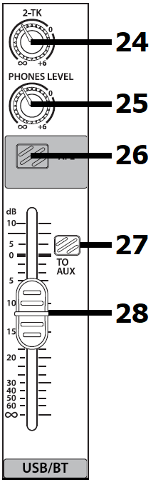 2-TK/USB/BT Channel
24. 2-TK Adjusts the level of the 2-TK input (L+R RCA input) to the Main L/R outputs
25. PHONES LEVEL Adjusts the volume of the headphones and monitor outputs
26. AFL After Fade Listen: routes USB player/recorder or BT wireless receiver output to the headphones and monitor outputs and LED VU meters.
27. TO AUX When pressed in, this will route the USB player/recorder or BT wireless receiver to the AUX output. Ideal for sending guide tracks or prompts to stage monitors.
28. USB/BT Fader Controls the playback output volume of the USB Media Player/Recorder or BT wireless receiver for playback
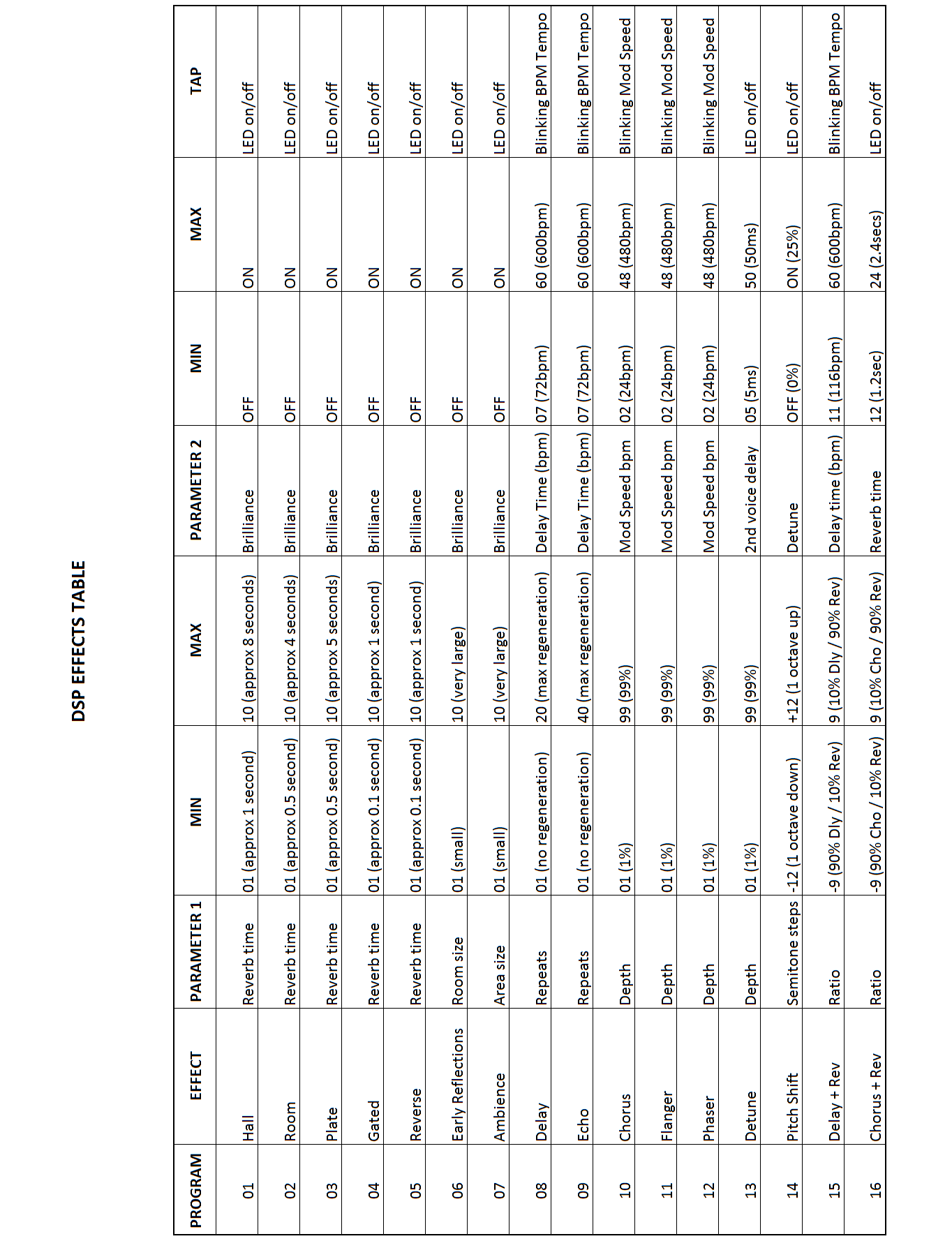
DSP Effects (FX)
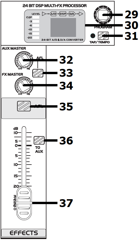
29. PROGRAM Rotate to select a preset and push to select. Push again to select parameter 1. A single red dot will flash in the display. Rotate to set value and push to accept value.
30. Display LED numeric display to show effect status Includes an LED VU meter to show effects bus level.
31. TAP/TEMPO Tap button 3 or more times in time with music to set repeats of delay effects or press this button to access parameter 2 on other effect patches (see DSP Effects Table section). The tempo will be indicated by the adjacent flashing LED.
32. AUX MASTER Master volume control for mix of all AUX signals
33. AFL After Fade Listen: routes AUX output to the headphones and monitor outputs and VU meters.
34. FX MASTER Master volume control for output of DSP FX
35. AFL After Fade Listen: routes DSP FX output to the headphones and monitor outputs and VU meters
36. TO AUX Press in to send DSP FX output to the AUX bus
37. EFFECTS Fader Controls the output of the DSP FX to the main mix
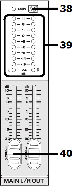
Main Output
38. +48V Phantom power switch. Press in to enable +48V to all XLR channel inputs to power condenser microphones or DI boxes.
39. VU Meters LED level meters for main output or PFL/AFL monitoring
40. MAIN Faders Left + Right faders for main output level
Rear Panel
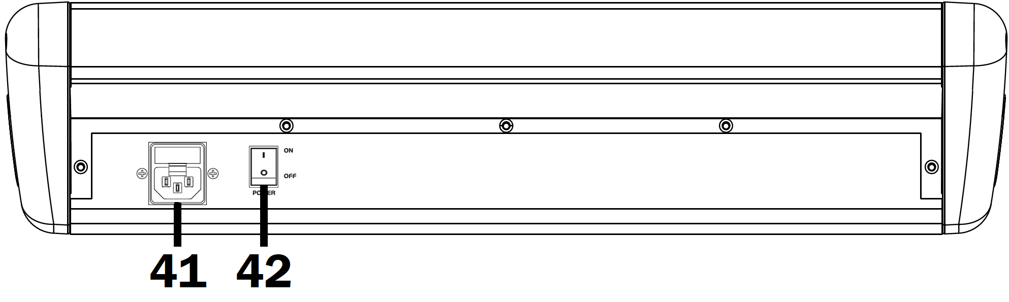 41. IEC mains inlet and fuse holder Connect the supplied power
42. Power on/off switch Turn down main level controls before powering up or powering down.