This unit has been designed to offer professional quality performance
with open flexibility to address a wide range of sound reinforcement
applications. Please read this manual and keep fit or reference to gain
the best results from this equipment and avoid damage through misuse.
Features
- 2 inputs, 6 outputs, fully balanced
- Independent parametric EQs
- Delay and Compressor/Limiter/Gate functions
- All inputs/outputs independently controlled
- Controllable via front panel, USB or LAN
- PC editing software included
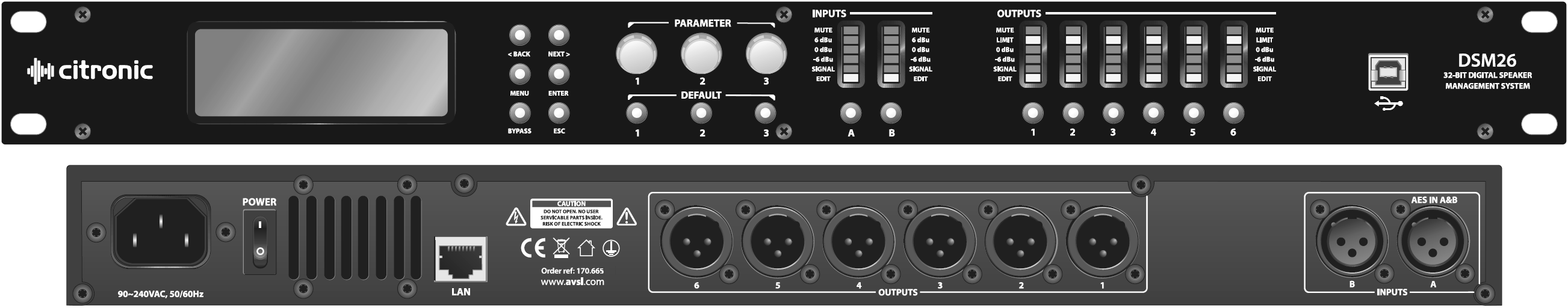
Front Panel Controls and Connectors
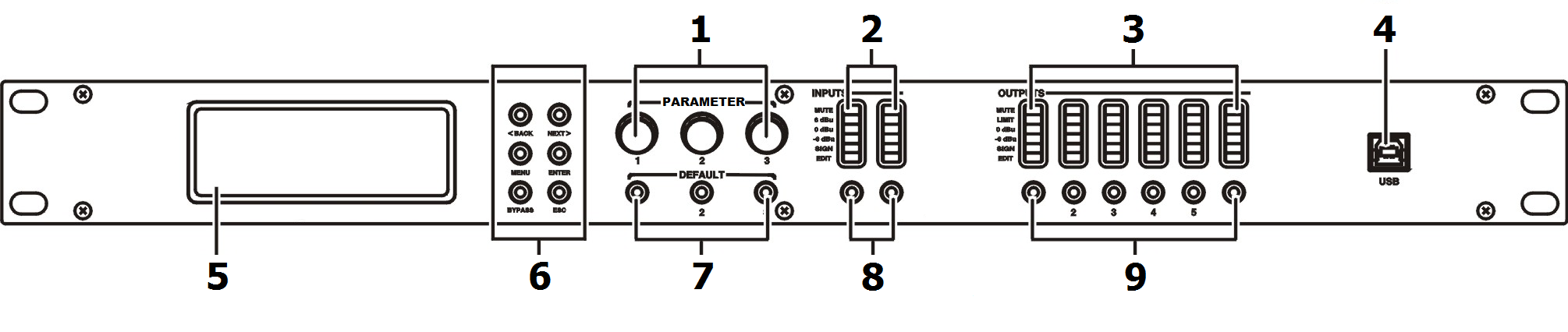
1. Rotary Encoders – 3 parameter adjust and menu navigation controls
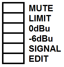
2. Input channel LEDs
3. Output channel LEDs
4. USB connection - Type B connector for linking to PC
5. LCD Display - Displays parameters and programming menu
6. Menu navigation buttons:
- BACK – selects previous menu item
- NEXT – selects next menu item
- MENU – Enter menu
- ENTER – Confirms selection
- BYPASS – bypasses process for comparison with unaffected signal
- ESCAPE – escapes from current screen
7. Default buttons
8. Input EDIT/MUTE key - Press to mute, press & hold 3sec to edit
9. Output EDIT/MUTE key - Press to mute, press & hold 3sec to edit
Rear Panel Controls and Connectors
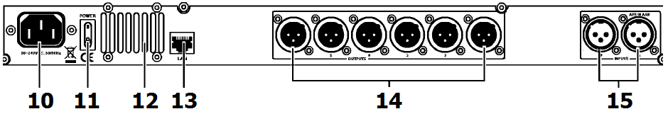
10. IEC connector - Mains inlet
11. Power switch - Switches mains power to the DSM26
12. Ventilation grille - Do not cover or obstruct airflow to this vent
13. RJ45 connector - LAN Connection to PC or other DSM2-6
14. Output connectors - Balanced XLR output connectors
15. Input connectors - Balanced XLR input connectors (analogue or AES
digital on input A)
Panel Operation
Input Parameter Setting
Pressing a Mute/Edit button will Mute or un-mute that specific input.
Press & hold the MUTE/EDIT key for IN A or IN B for 3 seconds to enter
edit mode.
Using the BACK and NEXT navigation buttons will step through the various
menu options.
1. Input Name

Parameter 1 rotary control selects the letter or figure
Parameter 2 rotary control moves to the next or previous character
Press ENTER to confirm when the name is set as required
2. Input Delay
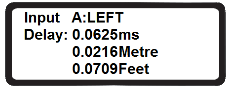
Delay 0-1000ms / 0-346m / 0-1134.88ft (independent per channel)
Parameter 1 rotary control performs fine adjustment
Parameter 2 rotary control performs coarse adjustment
 3. Input Polarity
Polarity [+] Normal / [-] Inverted (independent for each channel)
Parameter 1 rotary control toggles between + and - polarity
 4. Input Gain
Gain -40 to +6dB in 0.1dB steps (independent for each channel)
Parameter 1 rotary adjusts the Gain value
5. Input EQ
Input EQ1 - EQ8 (8 independent EQs for each channel)
Press BACK or NEXT buttons to step through EQ1 to EQ8
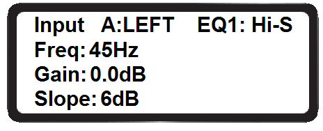 Parameter 1 rotary selects the filter type:
Parametric (PEQ), High-Shelf (Hi-S) or Low-Shelf (Lo-S)
Press ENTER to confirm the filter type and move down to parameter
settings.
Parameter 1 rotary control adjusts the cutoff frequency (20Hz to 20kHz)
Parameter 2 rotary control adjusts the gain (-30 to +15dB)
Parameter 3 rotary control selects bandwidth/slope (0.05-3.00oct or
6-12dB/oct)
Press ENTER to confirm parameter settings
 6. Noise Gate
Noise gate threshold -120 to +10dBu
Parameter 1, 2 or 3 rotary controls adjust the gate threshold
Output Parameter setting
Pressing a Mute/Edit button will Mute or un-mute that specific input.
Press & hold the MUTE/EDIT key for IN A or IN B for 3 seconds to enter
edit mode.
Using the BACK and NEXT navigation buttons will step through the various
menu options.
1. Output Name

Parameter 1 rotary control selects the letter or figure
Parameter 2 rotary control moves to the next or previous character
Press ENTER to confirm when the name is set as required
 2. Signal Source
Select On or Off for signal input A and input B
Parameter 1, 2 or 3 rotary control selects on or off status
Press ENTER to toggle between input A and input B
 3. Output Gain
Gain range -40 to +15dBu
Parameter 1 rotary control adjusts output gain
4. Output Polarity

Polarity [+] Normal / [-] Inverted (independent for each channel)
Parameter 1 rotary control toggles between + and - polarity
5. Output Delay

Delay 0-1000ms / 0-346m / 0-1134.88ft (independent per channel)
Parameter 1 rotary control performs fine adjustment
Parameter 2 rotary control performs coarse adjustment
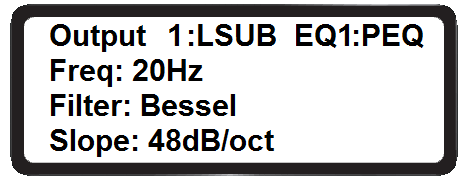
6. Crossover HPF
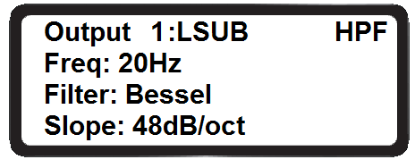 Crossover High-pass filter settings (independent
per channel)
Crossover High-pass filter settings (independent
per channel)
Parameter 1 rotary control adjusts cutoff frequency (20Hz-20kHz)
Parameter 2 rotary control sets filter type (Linkwitz-Riley, Bessel,
Butterworth)
Parameter 3 rotary control sets the slope gradient (12/18/24/48dB per
octave)
7. Crossover LPF
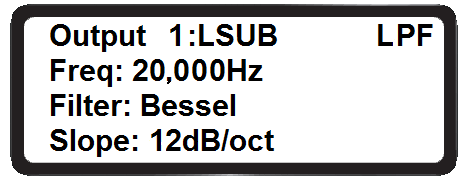 Crossover Low-pass filter settings (independent
per channel)
Crossover Low-pass filter settings (independent
per channel)
Parameter 1 rotary control adjusts cutoff frequency (20Hz-20kHz)
Parameter 2 rotary control sets filter type (Linkwitz-Riley, Bessel,
Butterworth)
Parameter 3 rotary control sets the slope gradient (12/18/24/48dB per
octave)
8. Output EQ
Output EQ1 - EQ6 (6 independent EQs for each channel)
Press BACK or NEXT buttons to step through EQ1 to EQ6
 Parameter 1 rotary selects the filter type:
Parametric (PEQ), High-Shelf (Hi-S) or Low-Shelf (Lo-S)
Press ENTER to confirm the filter type and move down to parameter
settings.
Parameter 1 rotary control adjusts the cutoff frequency (20Hz to 20kHz)
Parameter 2 rotary control adjusts the gain (-30 to +15dB)
Parameter 3 rotary control selects bandwidth/slope (0.05-3.00oct or
6-12dB/oct)
Press ENTER to confirm the parameter settings.
9. Output compressor/limiter
Output Compressor or Limiter (independent for each channel)
 Parameter 1 rotary control selects Compressor or
Limiter. Press ENTER to confirm
Parameter 1 rotary control selects Compressor or
Limiter. Press ENTER to confirm
In Compressor mode, press BACK or NEXT buttons to toggle between 2
pages:
Page 1: Parameter 1 adjusts the Threshold (-30 to +20dBu)
Page 1: Parameter 2 adjusts the Attack (0.3 to 100ms)
Page 1: Parameter 3 adjusts the Release time (2x, 4x, 6x, 8x, 16x, 32x
Attack time)
Page 2: Parameter 1 selects Manual or Auto mode (Auto overrides Page 1
parameters)
Page 2: Parameter 2 adjusts the Clip Limiter (2dB to 12dB above
threshold)
Page 2: Parameter 3 adjusts the Ratio (1:1, 1:2, 1:4, 1:8, 1:16, 1:32,
1:64, 1:Max)
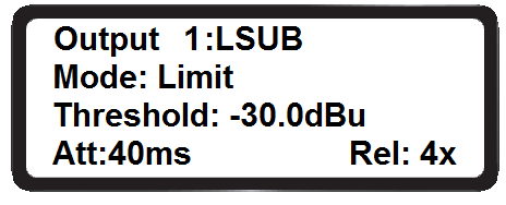
In Limiter mode, there is only one page of parameters.
Page 1: Parameter 1 adjusts the Threshold (-30 to +20dBu)
Page 1: Parameter 2 adjusts the Attack (0.3 to 100ms)
Page 1: Parameter 3 adjusts the Release time (2x, 4x, 6x, 8x, 16x, 32x
Attack time)
Main Menu
Pressing the MENU button enters the main menu for system settings.
The BACK and NEXT buttons or Parameter 1 to navigate through the
sub-menus. Press ENTER to select an option.
- X-over (crossover) 1) Load program, 2) Store program, 3) Erase
program.
Program copy Copy all input and output settings from a stored
program to another program.
Parameter 1 selects source, Parameter 2 selects target, Press ENTER to
copy.
Channel copy Copy all parameter settings from any input or output
channel to another channel.
Parameter 1 selects source, Parameter 2 selects target, Press ENTER to
copy.
- Input Parameter 1 selects between Analogue or Digital (AES) input
type.
- Security Parameter 1 = character, Parameter 2 = previous/ next,
Press ENTER = lock (or unlock).
- System 1) Backlight Keep On or Auto-off after 25s.
2) System info. Press ENTER to see the system information
3) Temperature: Parameter 1 adjusts the maximum temperature before
cut-out
4) Filter Display: Parameter 1 selects filter Bandwidth or Q
parameter display
5) Scene change: Enable/disable buttons 1, 2 and 3 as hot keys for 3
favourite programs
6) Scene key setup: Use Parameter 1, 2 and 3 to set Favourites 1, 2
and 3
7) WIFI Factory Reset – not used (future development)
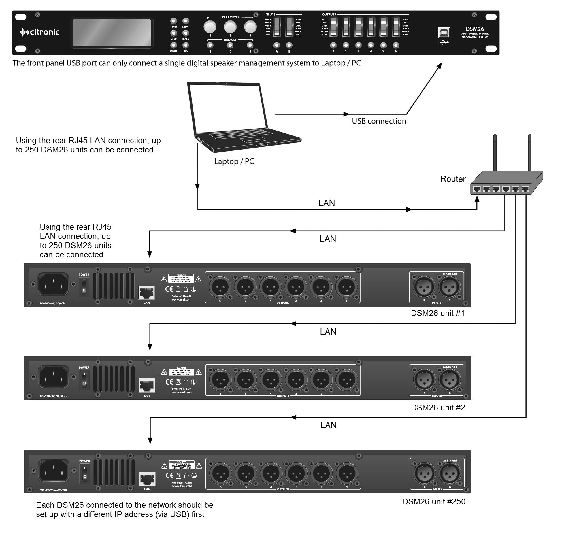
PC Software Operation
Setting up
The Citronic DSM26 can be operated individually from a PC via USB and
can also be linked in multiples over a wider, long-distance network
via LAN connection. A maximum of 250 units may be linked together by
this method.
If connecting via LAN, see the “LAN Setup” section further on in this
document.
Before connecting a DSM26 via USB, install the software from the
supplied disc.
Locate the driver file “PL2303_Driver” and double click to install
(this will usually require a re-start once installed)
Connect the DSM26 via USB or LAN as shown below and double click the
file named “DSP Ver 3.9”
Screen Shot
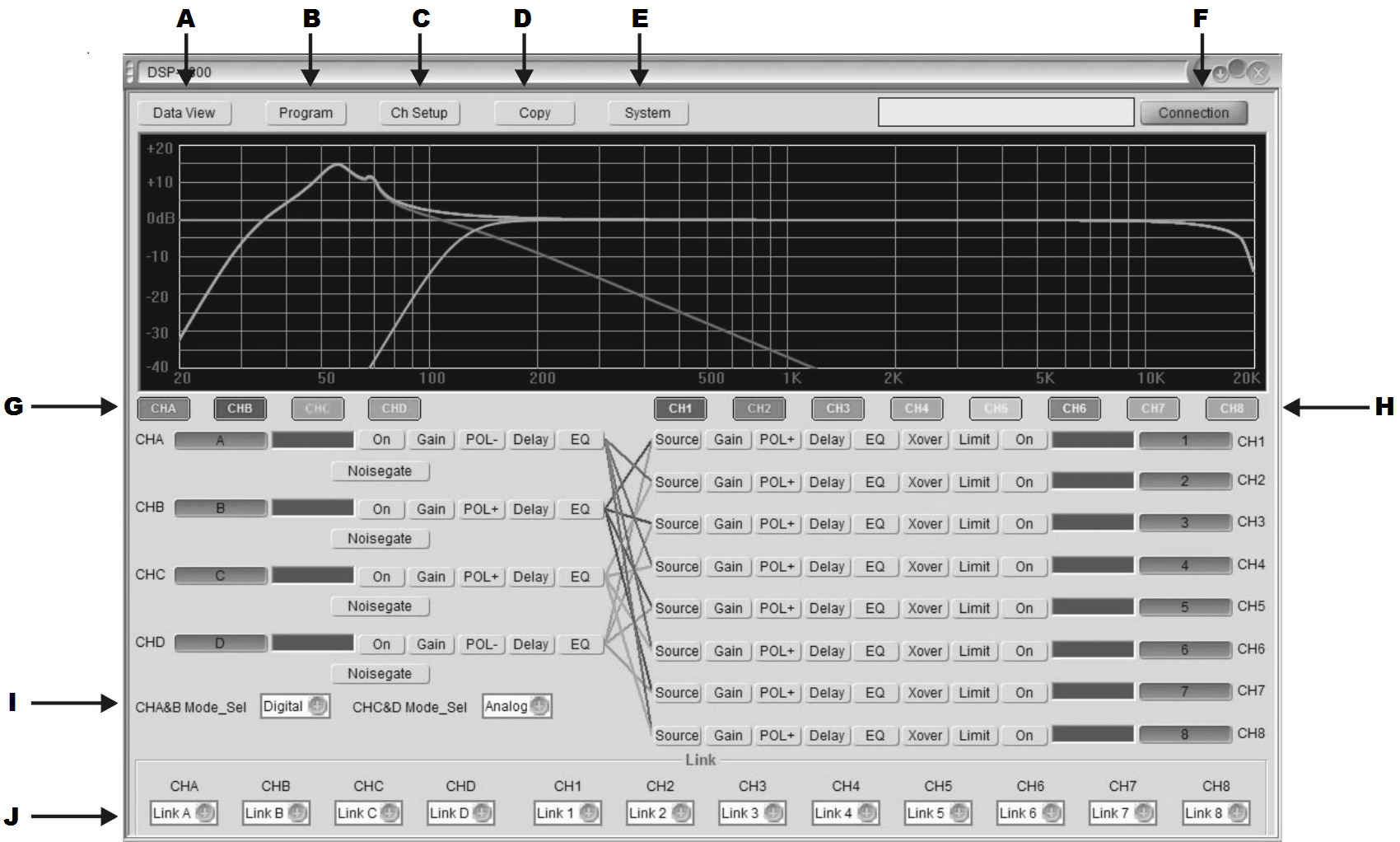
Note: 4 input, 8 output software version shown – will default to 2 in, 6
out when DSM26 is connected
B
|
Save / Load Program menu
|
G
|
Input edit select
|
C
|
Channel setup
|
H
|
Output edit select
|
D
|
Copy channel
|
I
|
Input source type setting
|
E
|
System menu
|
J
|
Channel connect
|
Connection
In order for the PC to communicate with the DSM26, it is necessary to
establish a connection.
Click on “Connection” (F)

The following menu will be displayed
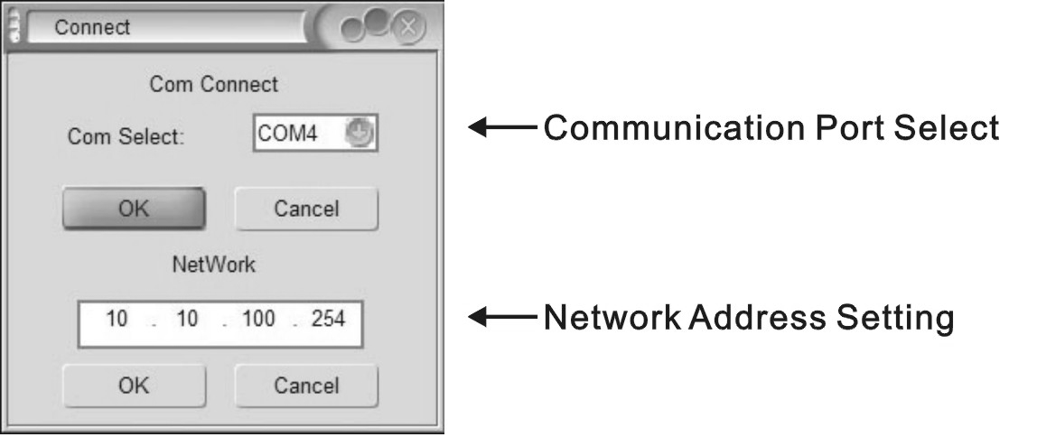
The software will normally be able to detect the correct COM port and
this will be displayed.
Click OK to confirm the USB connection between PC and DSM26. If
unsuccessful, try a different COM port from the list.
If COM port is not detected automatically, open the PC’s Hardware Device
Manager.
(e.g. “Start-Settings-Control Panel-System-Hardware-Device Manager” or
type “Device Manager” into the search box)
Look in “Ports” to identify which port is being used for the DSM26.
Select the correct port for the connected DSM26 in the Connection menu
(COM4 is shown in the above example)
If connecting via LAN, enter a workable IP address which is not occupied
by other equipment into the “Network” field.
Program Menu
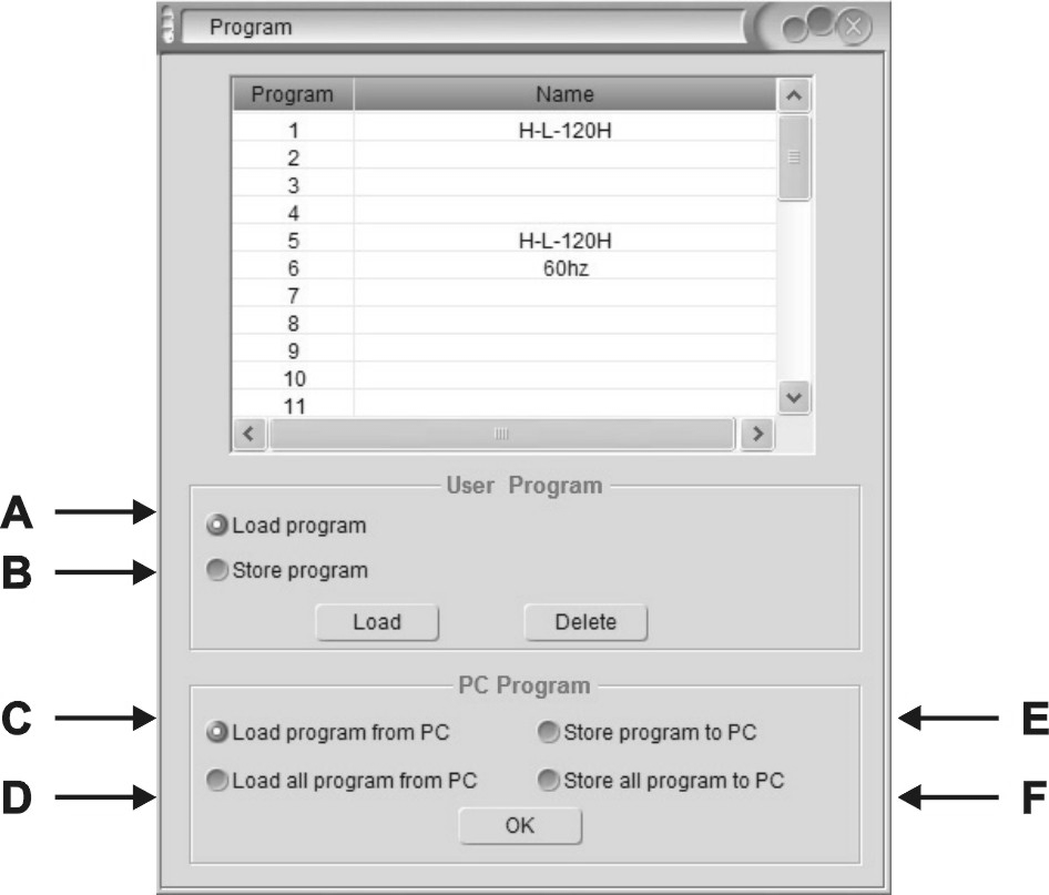 Clicking on the Program button at the top of
the main screen will open the following window.
Clicking on the Program button at the top of
the main screen will open the following window.
B
|
Save/Delete group user data or effect data from device
|
C
|
Load group user data or effect data from PC
|
D
|
Load all group user data or effect data from PC
|
E
|
Save group user data or effect data from PC
|
F
|
Save all group user data or effect data from PC
|
To load a program, check button A, click on the program in the list in
the top half of the window and then click the Load button.
To delete a program, click on it in the list in the top half of the
window and then click the Delete button.
To save a program after editing, check button B, select a blank program
or one for over-writing, type a name in the text field and click the
Save button.
Selected programs or All programs may be saved to PC or loaded from PC
by checking buttons C, D, E or F and clicking “OK”
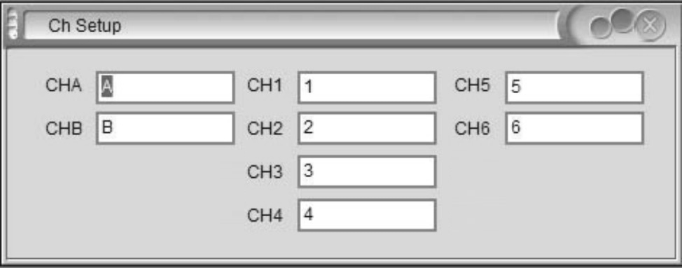 Channel setup
Clicking the Ch Setup button will open the widow shown opposite.
Click in each window and type a name for each input and output, then hit
return to rename that channel
Copy function
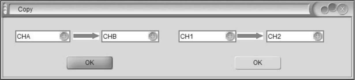
Clicking the Copy button in the main screen will open the widow
shown opposite.
Select inputs (left side) or outputs (right side) to copy from and to
and click OK to copy all settings across.
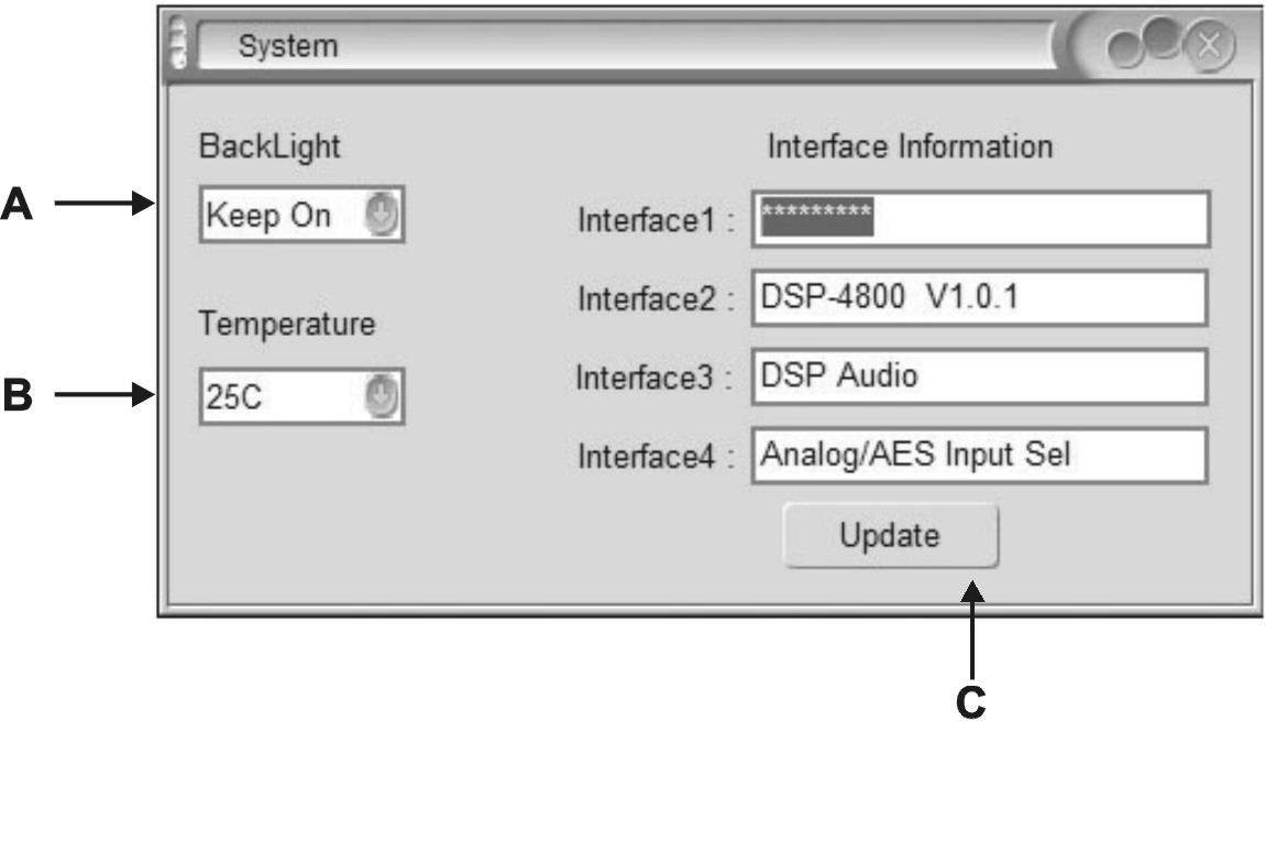 System menu
Clicking the System button in the main screen will open the widow
shown opposite.
B
|
Select cutoff temperature for the device
|
C
|
Interface information is shown in the 4 fields on the right side of
the window and can be edited by typing directly in each and clicking Update
|
Channel Functions
Clicking on an input channel button switches the button between its own
colour or grey.
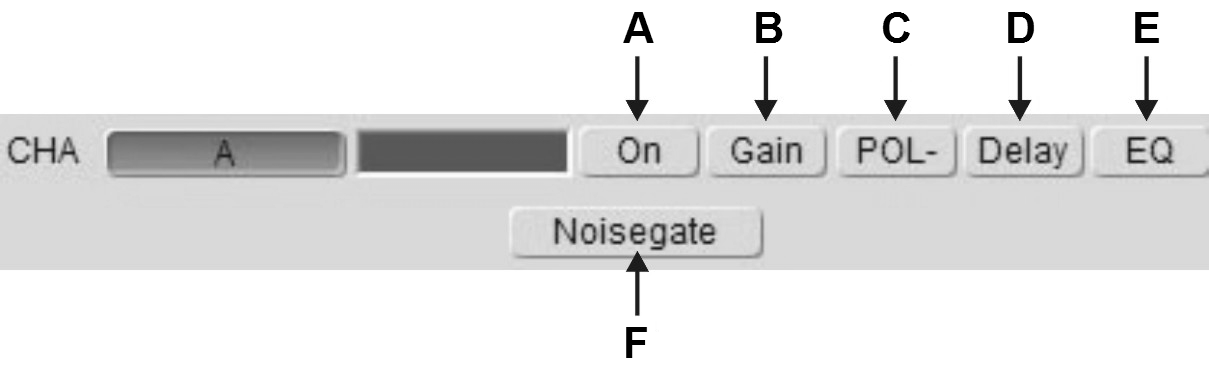 When it is grey, its frequency curve will not be
displayed in the top window. Clicking on any of the channel functions
button will open an editing window for that function
When it is grey, its frequency curve will not be
displayed in the top window. Clicking on any of the channel functions
button will open an editing window for that function
B
|
Input Gain setting
|
C
|
Normal or Inverted polarity select
|
D
|
Input Delay time setting
|
E
|
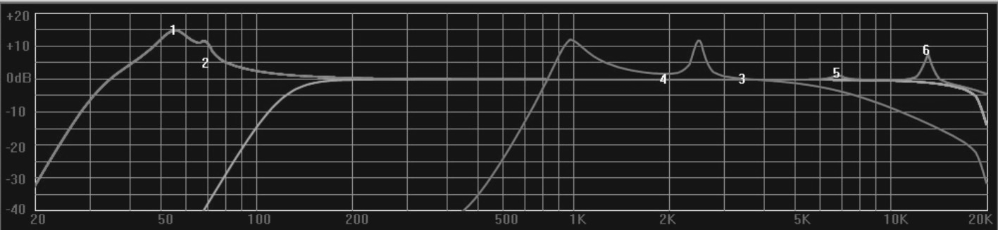
EQ edit - click & drag EQ 1-8 on the curve graph to adjust centre frequency or stretch bandwidth (see below)
|
F
|
Noise gate setting
|
In EQ edit mode, click and drag EQ numbers on the curve graph to adjust
the centre frequency for each filter
Clicking on an output channel button also switches the button between
its own colour or grey.
When it is grey, its frequency curve will not be displayed in the top
window. Clicking on any of the channel functions button will open an
editing window for that function.
B
|
Output Gain setting
|
C
|
Normal or Inverted polarity select
|
D
|
Output Delay time setting
|
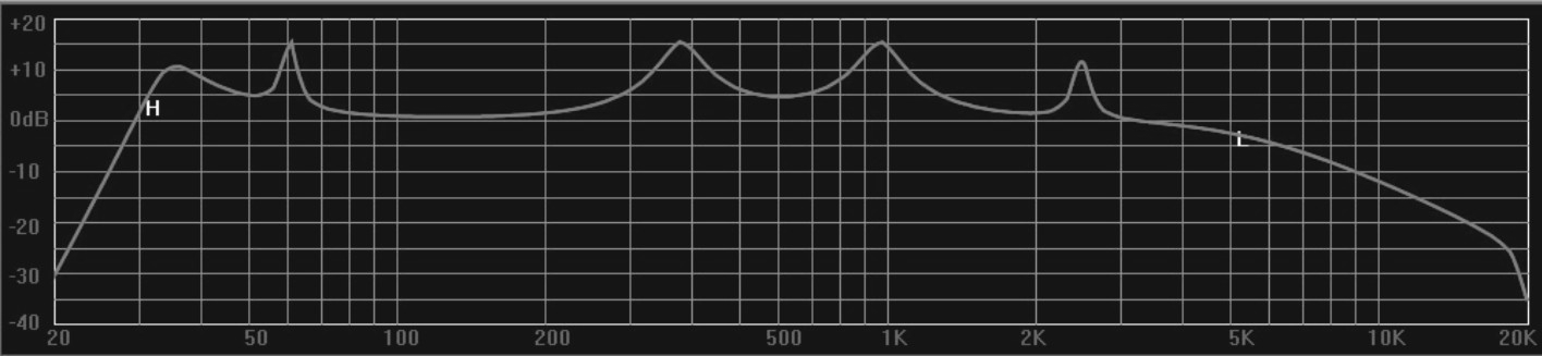
E
|
EQ edit - click & drag EQ 1-8 on the curve graph to adjust centre frequency or stretch bandwidth
|
F
|
Crossover edit - click and drag H or L on the curve graph to adjust centre frequency for each filter (see below)
|
G
|
Compressor/Limiter setting
|
Clicking on any function button will enter editing mode for that
function.
In Crossover edit mode, click and drag H or L to adjust the centre
frequency for each filter
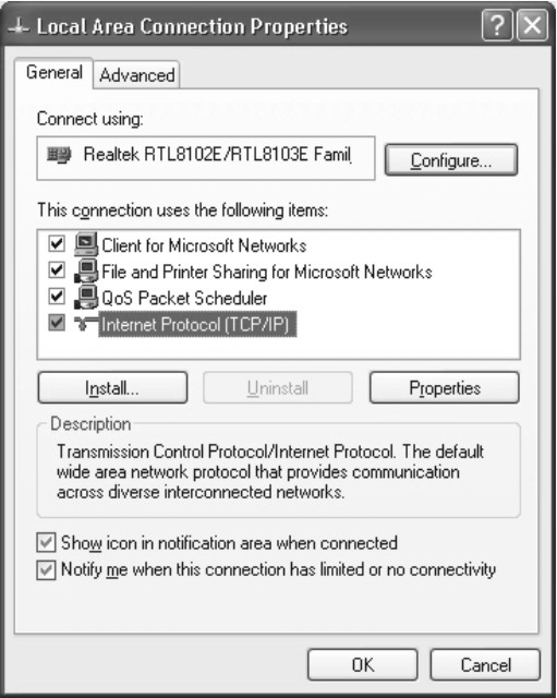 LAN setup
On the PC that is to be connected with the DSM26 (or multiple units),
navigate to the network adaptor properties.
e.g. in Windows 10, click the start button and click the settings icon
(cog symbol)
Select Network & Internet and Ethernet.
Select Change Adapter Options, right click the relevant connection
and select Properties.
The window opposite should appear, showing network adaptor options.
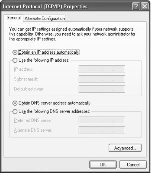
Right click on TCP/IP and the window opposite will appear.
Ensure that the button for Obtain an IP address automatically
This will ensure that the PC will connect to the DSM26 unit as a LAN
host.
The next step is to connect the PC to the DSM26 unit directly via LAN
cable.
In the DSM26 software main screen, click the Connection button.
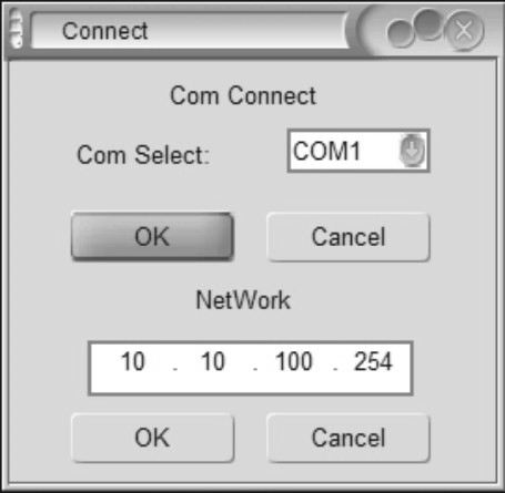 The window opposite will open, showing the COM
port and IP settings.
The window opposite will open, showing the COM
port and IP settings.
Click OK below the auto-detected IP address and the DSM26 will connect.
Once connected directly to the PC via LAN cable, it is possible to
access the DSM26 network
adaptor from the PC by opening a browser window (IE, MS Edge or Chrome
etc.)
Type in the (auto-detected) IP address of the DSM26 into the address bar
of the browser.
(e.g. as shown in the connection window opposite, this would be
“http://10.10.100.254”)
A security window will open as follows…
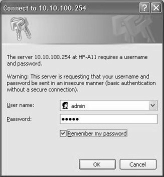
Both User name and Password are “admin” by default.
Once logged into the DSM26, an edit window will open, as shown below.
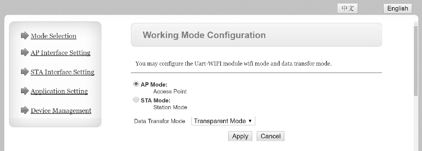
If the display is not in English, click the English button. There are
many advanced settings within this menu, which should only be edited by
the network
administrator but the basic LAN settings are easily
set as follows.
Click on the “AP Interface Setting” link and a new window will open to
edit network settings.
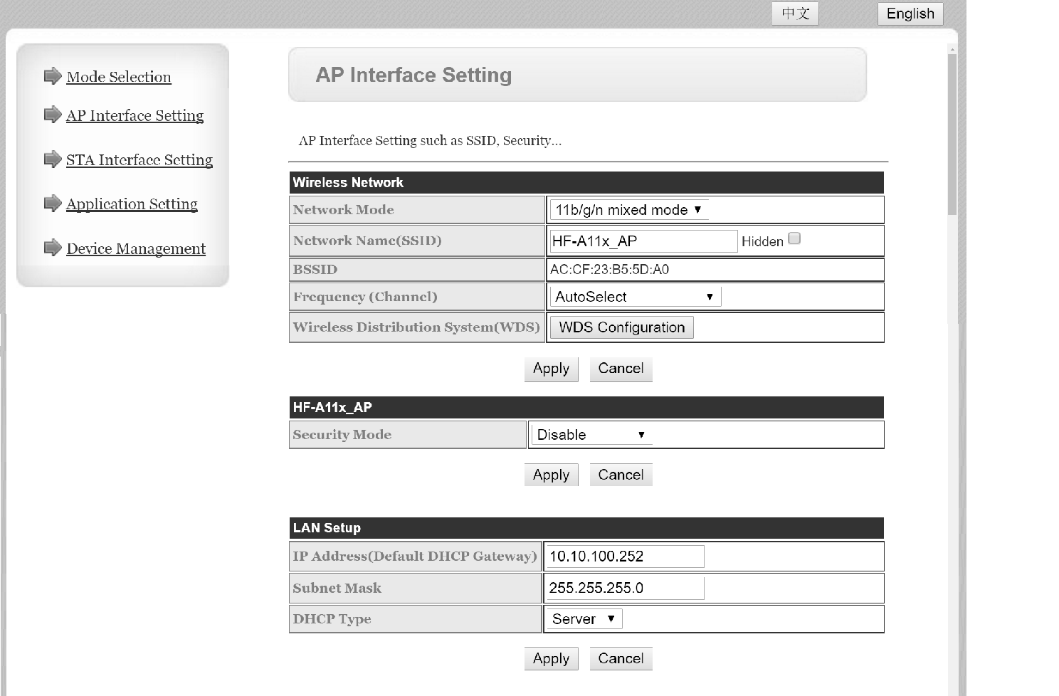
In the AP Interface Setting window, it is possible to edit the IP
address of the DSM26 for LAN connection. Enter a new valid IP address
into the top field of the “LAN Setup” section (Wireless does not apply
to the DSM26 unless modified)
Click “Apply” and a message will appear advising…
“Set Successfully, Restart to use new setting”
Click on the “Device Management” link.
(the login user name and password can be edited here)
Click on the “Restart” button and the DSM26 will restart.
Note: to log back in, it will be necessary to input the new IP address
into the browser address bar (and new user name and password if they
have been edited)
The unit can now be connected to the main LAN network and connected by
its IP address in the DSP Ver3.9 application.
