Thank you for choosing a Citronic PLX2800 power amplifier as part of your sound reinforcement system. This high output amplifier is designed to offer high quality, dependable service for mobile and installed systems. Please read this manual fully and follow the instructions to achieve the best results with your new purchase and to avoid damage through misuse.
Front Panel
| | |
|---|
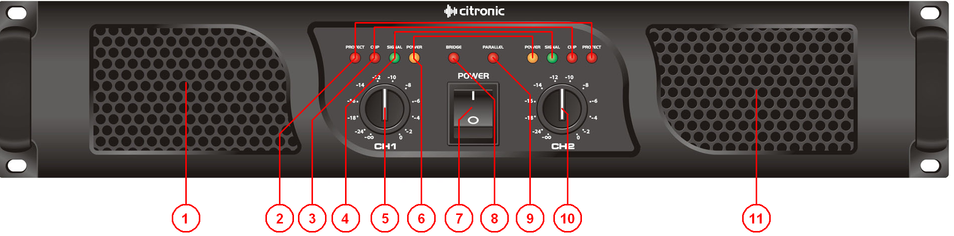
| 1. | Cooling vent | 7. | Power switch |
| 2. | Protect LED's | 8. | Bridge LED |
| 3. | Clip LED's | 9. | Parallel LED |
| 4. | Signal LED's | 10. | CH2 gain control |
| 5. | CH1 gain control | 11. | Cooling vent |
| 6. | Power LED's | | |
Rear Panel
| | | |
|---|
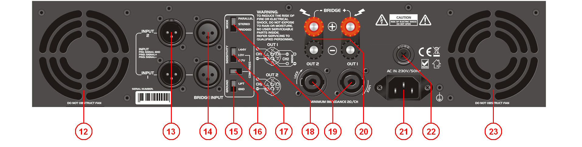
| 12. | Cooling fan | 18. | Parallel/Stereo/Bridge mode switch |
| 13. | Parallel signal outputs | 19. | Speaker outputs 1 and 2 |
| 14. | Signal inputs | 20. | 4mm binding post speaker outputs (inc. Bridge) |
| 15. | Ground lift switch | 21. | IEC mains inlet |
| 16. | Compress (clip limiter) switch | 22. | Mains fuse holder |
| 17. | Input sensitivity switch | 23. | Cooling fan |
Operation
Connect speaker cabinets to channel outputs using good quality leads via the SPK connector or binding posts and ensure that the combined load on each channel is no lower than 2Ω.
For speaker loads connected in parallel… 1/speaker impedance + 1/speaker impedance… = 1/TOTAL impedance
Therefore… 8Ω + 8Ω = 4Ω total
4Ω + 4Ω = 2Ω total
8Ω + 8Ω + 8Ω + 8Ω = 2Ω total
Both channels can be used to drive a single load at the combined volume of each by switching to BRIDGE mode. In this mode, the input is on channel 1 and output from CH1 SPK connecter (pins 1+ and 2-) or across the red “+” terminals as indicated on the rear panel - WARNING - Minimum load for bridge mode is 4Ω
Connect each signal input from mixer or other line level source via the XLR connectors on the rear panel using good quality signal leads. Depending on output level of the mixer, select the appropriate sensitivity on the rear panel.
For protection in high power situations, the onboard COMPRESS function may be switched in to protect from overload.
In situations with excessive mains hum coming through the speakers, it may help to switch the GROUND to the LIFT position. This is may help in some situations but otherwise, it is preferred to be switched to GND.
XLR inputs and outputs for each channel are wired in parallel, allowing signal to be carried forward to further amplifiers.
Connect the amplifier to a mains outlet, ensuring that the IEC lead is earthed, in good condition and connected securely.
With channel gain controls turned fully down, switch on the power to the amplifier. This unit has a “soft-start” function which makes some checks before engaging power to the amplifiers, which may take a few seconds.
With mixer (or other signal source) levels turned down, gradually increase the amplifier’s channel level controls to the required level (normally full) and then gradually increase the signal level from the mixer or sound source until sound can be heard through the speakers and then continue increasing up to the required level.
During use, green “SIGNAL” LEDs will illuminate to show when a signal is present and yellow “CLIP” LEDs illuminate if the output is reaching clip level. If the red CLIP LEDs illuminate more than very briefly, reduce the volume until they hardly light up at all.
If the internal protection circuitry detects a fault in the speakers or amp, the channel(s) will enter Protect Mode and red “PROTECT” LEDs will illuminate on the front panel to show this. Switch the amplifier off and check the entire system (including leads) before powering up again. If still in Protect Mode, seek advice from qualified service personnel.
Before powering down, turn the channel gain controls fully down to avoid loud noises when switching off.
