Thank you for choosing a Citronic D1000 power amplifier as part of your
sound reinforcement system. Custom class-D circuit design provides an
efficient amplifier within a compact and lightweight form factor. Please
read this manual fully and follow the instructions to achieve the best
results from your amplifier and to avoid damage through misuse.

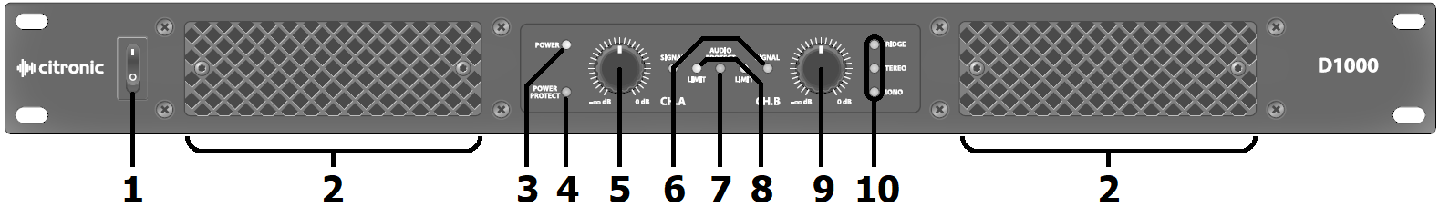
Front Panel
|
|
|
|
| 1. |
Power on/off switch |
6. |
Signal present indicators |
| 2. |
Cooling vents – do not cover or obstruct |
7. |
Audio Protect indicator |
| 3. |
Power on indicator |
8. |
Audio Limiter indicators |
| 4. |
Power Protect indicator |
9. |
CH.B output level control |
| 5. |
CH.A output level control |
10. |
Amplifier operating mode LEDs |
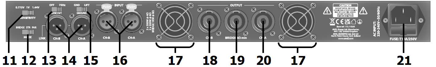
Rear Panel
|
|
|
|
| 11. |
Input sensitivity switch 0.775V / 1.00V / 1.44V |
17. |
Cooling fan vents – do not cover or obstruct |
| 12. |
Amplifier mode switch – Bridge / Stereo / Parallel |
18. |
CH.B stereo or parallel output - SPK connector |
| 13. |
75Hz low cut filter on/off switch |
19. |
Bridge mono output - SPK connector |
| 14. |
CH.A+B signal link out (XLR balanced/unbalanced) |
20. |
CH.A stereo or parallel output - SPK connector |
| 15. |
Ground Lift switch |
21. |
IEC mains power inlet & fuse holder |
| 16. |
CH.A+B signal input (XLR balanced/unbalanced) |
|
|
Operation
Connect speaker cabinets to channel outputs (18, 19) using good quality
Speakon® leads and ensure that the combined load on each
channel is no lower than 2Ω.
For speaker loads connected in parallel… 1/speaker impedance + 1/speaker
impedance… = 1/TOTAL impedance.
Therefore… 8Ω + 8Ω = 4Ω total
4Ω + 4Ω = 2Ω total
8Ω + 8Ω + 8Ω + 8Ω = 2Ω total
The rear panel has a MODE switch (13), which determines the way that the
amplifier operates. The standard operating mode is STEREO, with each
input feeding its relevant speaker output.
PARALLEL mode sums both inputs together in mono so that each
amplifier channel receives a mix of both inputs.
Also, both channels can be combined to drive a single load at higher
power by selecting BRIDGE mode. In this mode, the input is on
channel 1 and the output is from the OUT 1 speaker connecter as
indicated on the rear panel (wired to pins 1+ and 2-) WARNING – The
minimum load for BRIDGE mode is 4Ω.
Below the MODE switch is a SENSITIVITY switch (15), which has 3 settings
for different input levels.
The standard setting is 1.0V and further settings for 1.4V and 2.0V
higher level inputs will reduce the input sensitivity.
When set to “on”, the LF PROCESSING switch provides a 2dB boost at 100Hz
for enhanced bass response.
Connect each signal input from mixer or other line level source via XLR
or 6.3mm jack connectors to the combo connectors (11, 17) on the rear
panel using good quality signal leads. Depending on output level of the
mixer, select the appropriate sensitivity on the rear panel. Wiring for
balanced or unbalanced inputs are as follows…
| Connector type |
Signal hot + |
Signal cold - |
Ground (GND) |
Unbalanced wiring |
| 6.3mm jack |
Tip |
Ring |
Sleeve |
Ring + Sleeve combined |
| XLR |
Pin 2 |
Pin 3 |
Pin 1 |
Pin 3 + Pin 1 combined |
Each channel input also has a corresponding XLR line output (12, 16) for
linking onto further amplifiers, as necessary.
XLR inputs and outputs for each channel are wired in parallel, allowing
signal to be carried forward to further amplifiers.
Connect the amplifier to a mains supply (9), ensuring the IEC lead is
earthed, in good condition and connected securely.
With Channel 1 + 2 controls (2, 6) turned fully down, switch on the
power to the amplifier (7). This unit has a “soft-start” function which
makes some checks before engaging power to the amplifiers, which may
take a few seconds.
With mixer (or other signal source) levels turned down, gradually
increase the amplifier’s channel level controls to the required level
(normally full) and then gradually increase the signal level from the
mixer or sound source until sound can be heard through the speakers and
then continue increasing up to the required level.
|
|
| PROT |
Protect mode |
| CLIP |
Signal clipping (overload) |
| SIG |
Signal present |
| POW |
Power on |
The LED indicators for each channel (3, 5) are as shown opposite.
In normal operation, the POW indicators will be on and the SIG
indicators will light when an input signal is present.
If the input signal is overloading the amplifier, this “clips” above the
available power limit.
When this happens, the CLIP indicators will light.
It is acceptable for CLIP indicators to flash very briefly in
response to loud peaks in the audio signal.
However, if they light for any longer than a brief instant or very
frequently, the input level should be reduced or channel level controls
on the front panel should be turned down until the regular clipping is
eliminated.
If the internal protection circuitry detects a fault in the speakers or
amp, the channel(s) will enter protect mode and PROT will illuminate
on the front panel to show this. Switch the amplifier off and check the
entire system (including speaker leads) before powering up again. If
still in Protect Mode, seek advice from qualified service personnel.
Each D1000 amplifier also has a backlit LCD display (4) on the front
panel with the following information for monitoring.
- Mains supply voltage
- Internal temperature of each amplifier channel
- VU signal meters for each channel
- Fan speed
Before powering down, turn the channel gain controls fully down to avoid
loud noises when switching off.
