This unit is designed to offer high quality, dependable service for
mobile and installed systems.
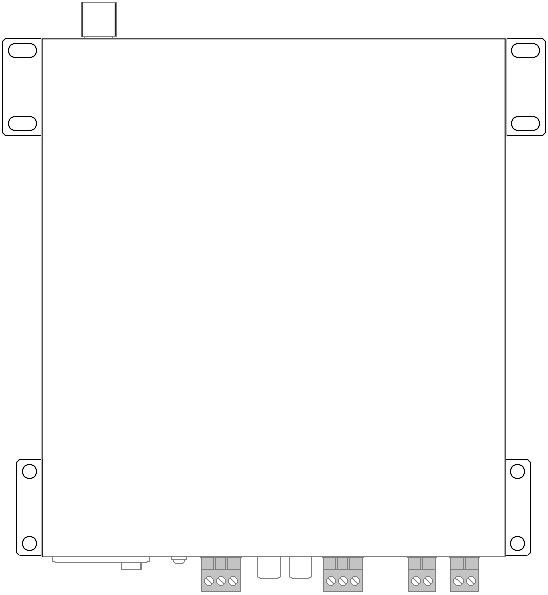
Rack Mounting
The US series amplifiers can be mounted into a 19” rack cabinet using
the supplied rack accessories.
As shown below, the 2 joining brackets link a pair of UM series
amplifiers together to form a full-width 1U rack-mount pair. One rack
ear can be mounted at each end for fixing to the rack strip.

Wall or under counter mounting
The rack mounting accessories can also be attached so that the amplifier
can be mounted against a wall or under a counter or work surface. To do
this, mount the rack ears with the tabs aligned with the top of the
housing to provide mounting holes to screw the amplifier to the
underside of a work surface or against a wall with the controls visible
vertically.
Front Panel
|
|
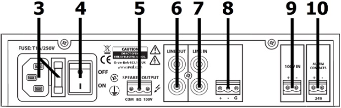
| 3. |
IEC power inlet and fuse holder |
| 4. |
Power on/off switch |
| 5. |
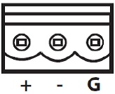
100V and 8Ω speaker output terminals |
| 6. |
LINE 4 RCA input |
| 7. |
CH3 6.3mm and screw terminals input |
| 8. |
CH2 6.3mm and screw terminals input |
| 9. |
CH1 Phantom-Mic/Line-Vox DIP switches |
| 10. |
LINE OUT RCA output |
Rear Panel
Connection and Setup
Set the rear power switch (4) to the “off” position and connect the rear
IEC inlet (3) to the mains using the supplied mains lead (or an
equivalent approved type). Check that the supply voltage is 170-264Vac
50Hz.
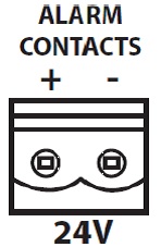
A pair of screw terminals is provided on the right side of the rear
panel for connection to an alarm system if required (10). This
connection will mute the LINE IN inputs but will not mute 100V IN (for
alerts) when 24V is present across the terminals.
(24V is a standard trigger voltage from most fire and security panels)
Note: Screw terminal blocks can be unplugged from the panel for
convenience during connection.
The US series slave amplifiers are designed to accept a single line
level audio input, such as the line output of a mixer or another
amplifier, as a means of expanding an existing sound system. The line
input can also be from a CD, mp3, DAB/FM tuner or other line level
source if that is the only audio source that is required.
Input connection is via Left + Right RCA sockets (7), which are summed
to mono for the output, or via a screw terminal input (8), which is
labelled “+ / - / G”.
For Unbalanced connection, connect the signal (core) wire to “+” and
connect the Ground (braid) to “- and G”.
 For Balanced connection, there will be 2 core
wires. Connect the hot (usually red) wire to “+” and the cold (white,
black or blue) wire to “-”. Then connect the Ground (braid) separately
to “G”.
For Balanced connection, there will be 2 core
wires. Connect the hot (usually red) wire to “+” and the cold (white,
black or blue) wire to “-”. Then connect the Ground (braid) separately
to “G”.
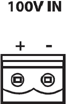
Another input method is provided via the 100V input terminals (9). This
is a pair of screw terminals (+/-) for connecting to the speaker line in
a 100V line system. Connect “+” to 100V and “-” to 0V or GND as you
would any 100V speaker. (there is internal protection to ensure that the
high voltage cannot cause damage to this input)
Caution: Do not connect 100V speaker output from this amplifier to its
own 100V input!
This type of input means that an existing 100V sound system can be
extended from any point along its output wiring without the need for
running additional signal cables and can also avoid problems associated
with signal degradation along low voltage audio cables.
Caution: Do not connect 100V speaker level to any other input - this
could damage the amplifier.
A twin RCA line output (6) is provided for connecting the mix of all
channels onto further amplifiers.
Speaker Connections
The US series amplifiers can be used either as 100V line amplifiers or
standard low impedance power amplifiers. These 2 configurations cannot
be used together, so decide which method will be used at the start.
100V Line Systems
For 100V line systems, connect the amplifier to the first speaker in the
system using double-insulated speaker wire which has adequate current
rating to handle the total output of the amplifier.
Connect the “100V” output terminal to the positive (+) connection of the
speaker and “COM” output to the negative (-) connection of the speaker
(14). Connect further speakers in parallel to the first speaker with all
positive terminals connected together and all negative terminals
connected together as shown below.
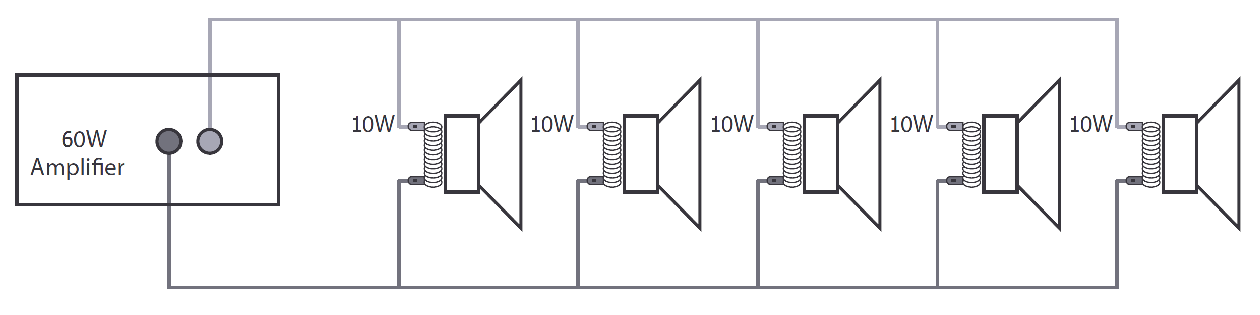
A 100V line speaker system can comprise of many speakers connected
together. The determining factor for how many speakers can be used on a
single amplifier is the power rating. For most purposes, it is advised
to connect as many speakers as needed with a combined wattage of no more
than 90% of the amplifier’s output power rating.
The terminals of a 100V speaker are connected to a transformer and in
some cases, this transformer may be “tapped” for different power
ratings. These tappings can be used to adjust the wattage (and output
volume) of each speaker in the system to help achieve the ideal total
power of the system for the amplifier.
Low Impedance Systems
The US-series amplifiers can alternatively provide an output for a
single 8Ω speaker by connecting the “8Ω” output to the positive (+)
speaker connection and “COM” output to the negative (-) speaker
connection. It is important to ensure that the speaker load is no lower
than 8Ω and that the power handling of the speaker is equal to or
greater than the output power of the amplifier.
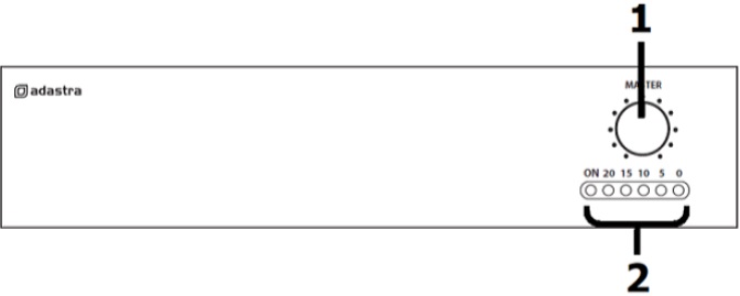
Operation
When all connections to the amplifier are made, turn the MASTER volume
control down (1) and switch on the power (4). A power LED will
illuminate at the left side of the audio output indicator LEDs (2).
Play an input signal (line or 100V) into the amplifier to check the
system. Turn up the MASTER volume control (1) gradually until the output
is heard through the speakers. The MASTER acts as the overall volume
control.
When not being used, turn down the MASTER control before powering down
to avoid loud clicks or pops.
