Thank you for choosing an Adastra RMS605 5-zone mixer-amp as part of
your sound system.
This 5-zone 100V power amplifier has the advantage of selectable global
or individual inputs and a paging microphone input.

Front Panel
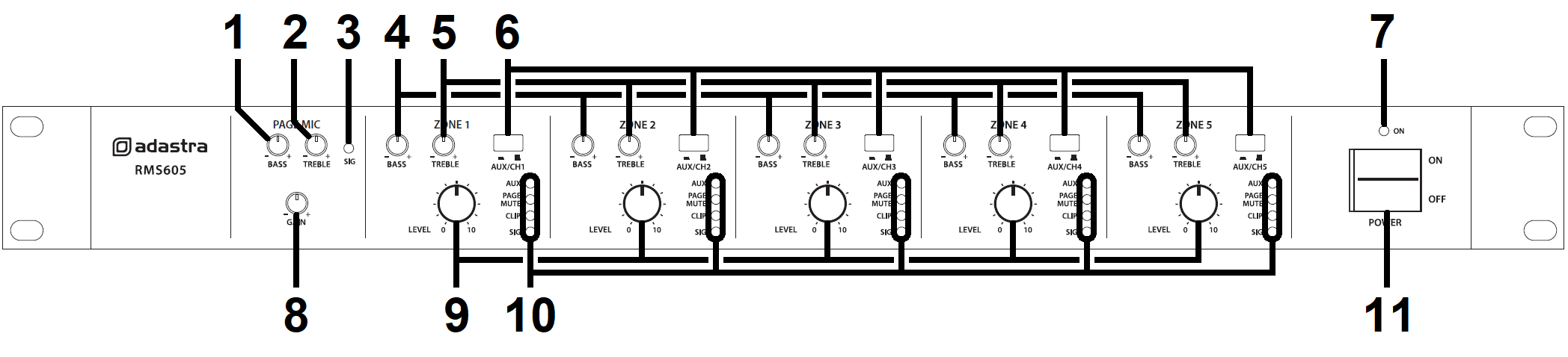
2.
|
TREBLE EQ – Paging Mic input |
8.
|
GAIN control – Paging Mic input
|
3.
|
Signal indicator – Paging Mic input |
9.
|
LEVEL control – Output channels
|
4.
|
BASS EQ – Output channels |
10.
|
Status indicators – Output channels
|
5.
|
TREBLE EQ – Output channels |
11.
|
Power on/off switch
|
6.
|
AUX/Individual channel input switch |
|
|
Rear Panel
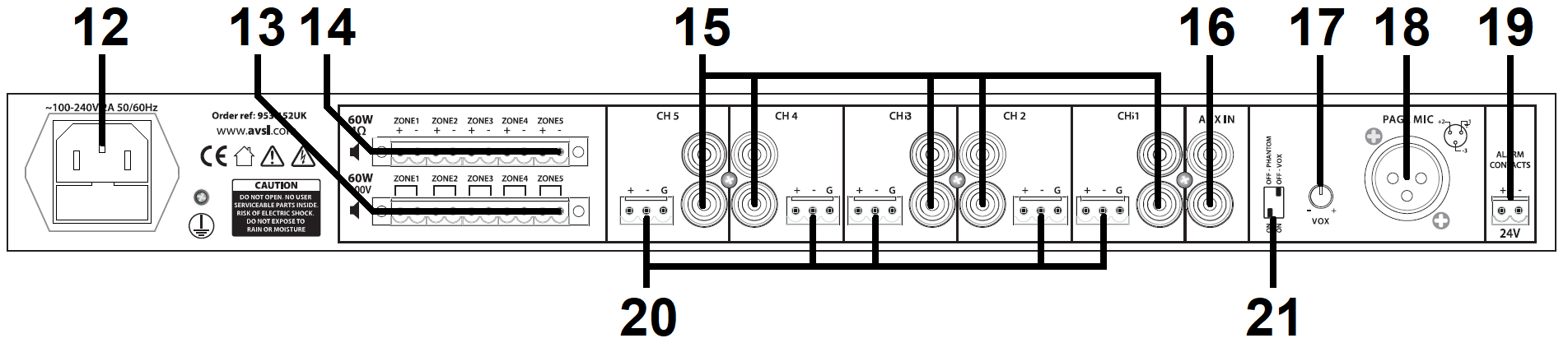
13.
|
100V speaker output terminals |
18.
|
Paging mic balanced XLR input |
14.
|
4Ω speaker output terminals |
19.
|
24V emergency mute terminals |
15.
|
Line level individual channel RCA inputs |
20.
|
Line level individual channel terminal inputs |
16.
|
Line level AUX RCA inputs |
21.
|
Phantom power and Vox DIP switches |
Connection
Ensure the Power (11) is switched off until all input and output
connections are in place.
Turn all output rotary level controls (9) fully down (anti-clockwise) to
avoid loud noises when switching on.
Set the BASS and TREBLE Tone controls (1, 2, 4, 5) to the vertical
position (zero)
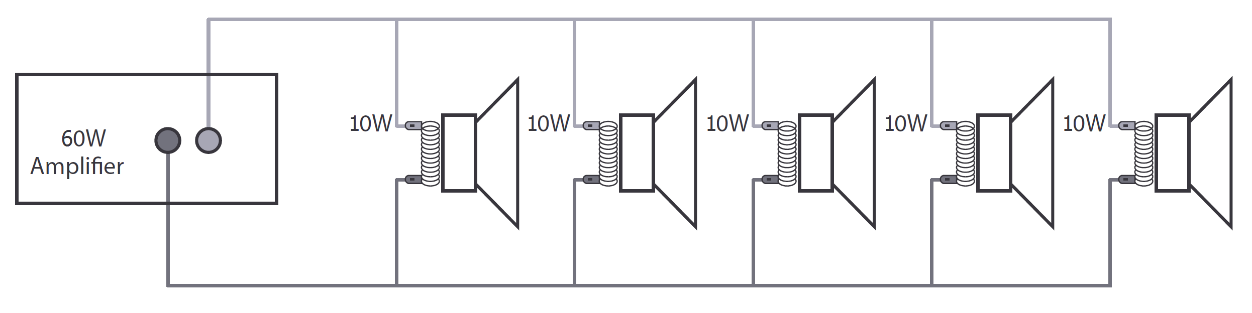
Loudspeakers should be connected to the RMS605 via screw terminals on
one of 2 removable modular connectors.
If the speaker(s) being connected is not 100V type, use the terminal
block marked “4Ω” for this channel (14).
Connect + and – wires to each speaker as indicated, ensuring that there
is no chance of strands shorting across terminals.
Important: Ensure that the load is no lower than 4Ω for each output.
This can be…
1 x 4Ω speaker 1 x 16Ω speaker
1 x 8Ω speakers 2 x 16Ω speakers wired in parallel (8Ω)
2 x 8Ω speakers wired in parallel (4Ω) 3 x 16Ω speakers wired in
parallel (5.3Ω)
4 x 16Ω speakers wired in parallel (4Ω)
Ensure that the connected speakers can handle 60W from each output.
 If the speaker(s) being connected to an output
channel are 100V type, use the terminal block marked “100V” for this
output channel. When connecting multiple 100V speakers to this output,
connect all speakers in parallel and ensure that the total load is below
54W.
If the speaker(s) being connected to an output
channel are 100V type, use the terminal block marked “100V” for this
output channel. When connecting multiple 100V speakers to this output,
connect all speakers in parallel and ensure that the total load is below
54W.
The wattage of each speaker can sometimes be adjusted via tappings on
the speaker (check the speaker’s documentation if unsure)
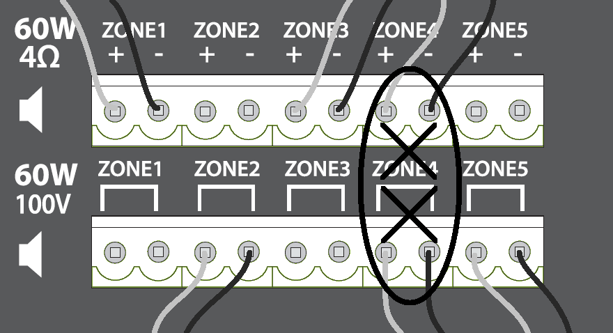
DO NOT connect to both 4Ω and 100V terminals for any individual output
channel
DO NOT mix 4Ω and 100V speakers on any single output.
THERE SHOULD BE NO CONNECTION MADE VERTICALLY ABOVE OR BELOW ANY OTHER
The RMS605 has 5 independent speaker output channels and can be used as
a 5-way slave amplifier.
Set each AUX/CH switch (6) to the ‘out’ position (for individual channel
input)
If connecting input to a channel via the pair of RCA inputs (15), these
will be summed to mono.
If connecting input to a channel via Euroblock terminals (20), the green
block may be removed from the panel for ease of handling.
Connect the signal “+” connection to the “+” screw terminal and the “-”
connection to the “-” screw terminal.
If there is a separate “ground” connection (i.e. balanced cable),
connect this to the “G” terminal.
Otherwise, for unbalanced connections, connect to “+” and “G” (or link
both “-” and “G” connections with a piece of wire)
If 2 or more channels will share the same audio source, there is an
option to connect this to the AUX input (16)
To route the AUX to any of the output channels, press the AUX/CH switch
to the ‘in’ position for each channel to receive the AUX input.
For convenience, the AUX/CH switch can be switched in our out whenever
AUX or individual channel input is needed.
For announcements and alerts, there is a PAGING MIC XLR input on the
rear panel (18)
Connect a microphone to this input if required and select the PHANTOM
power DIP switch (21) to “on” if it is a condenser microphone which
requires external phantom power from the XLR connector. Next to the
PHANTOM power DIP switch is the VOX DIP switch for voice override.
Switching this to the “on” position will cause all other inputs to be
muted when a sound is detected through the paging microphone input. The
amount by which this muting takes effect is adjusted using the “VOX”
rotary trim control (17)
The PAGING MICROPHONE input is always live to all output channels and
the GAIN (8) or signal level control and BASS + TREBLE tone
controls (1, 2) for this input are located on the front panel. If the
microphone is too quiet, increase the GAIN control or if it is too loud,
turn this control down. Adjust the BASS and TREBLE controls to achieve
the required tonal balance for the microphone output.
If available, connect a 24V trigger from an alarm panel to the alarm
contacts (17) to mute all except channel 1 in an emergency.
Connect the rear IEC inlet (16) to the mains using the supplied mains
lead (or an equivalent approved type).
Ensure that the supply voltage is correct for this equipment and that
the mains outlet is switched on.
Operation
When all signal and speaker connections are made, power up the RMS605
and gradually increase the LEVEL control of each channel to check the
output to the 5 zones. Adjust the levels to the required amount and use
the BASS and TREBLE controls to adjust the tone as necessary. For each,
the 12 o’clock position is zero and rotating left decreases the amount
of bass or treble whilst rotating right increases the amount of bass or
treble.
Test the PAGING MIC input by gradually adjusting the GAIN control to the
level needed to hear the microphone clearly through all channels. Again,
adjust BASS and TREBLE controls to ensure that the paging mic output is
clear and intelligible. If the VOX function is being used, adjust the
VOX control on the rear panel to the sensitivity required to hear
announcements over background music.
If needed, test the emergency mute contacts (19) by applying 24V across
the terminals as indicated – all inputs except for the paging microphone
should be muted.
After use, turn down all LEVEL controls before powering down to avoid
loud pops or clicks through the connected speakers.
