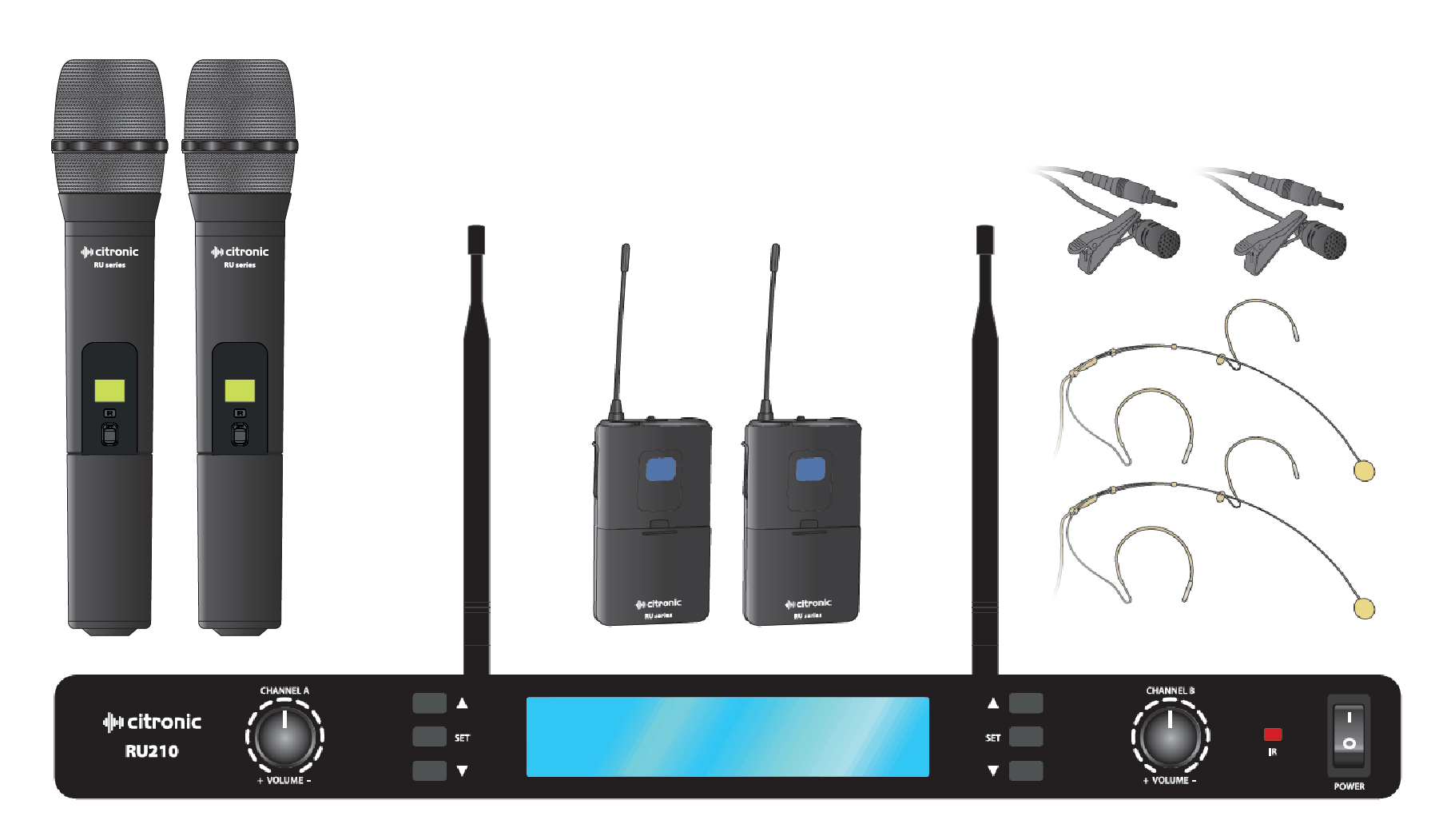
This professional wireless set provides 2 high quality microphones with a PLL tuned UHF radio system for freedom of movement without loss of audio quality. Please read this manual before using this equipment in order to avoid damage through incorrect operation and to get the best performance from your purchase.
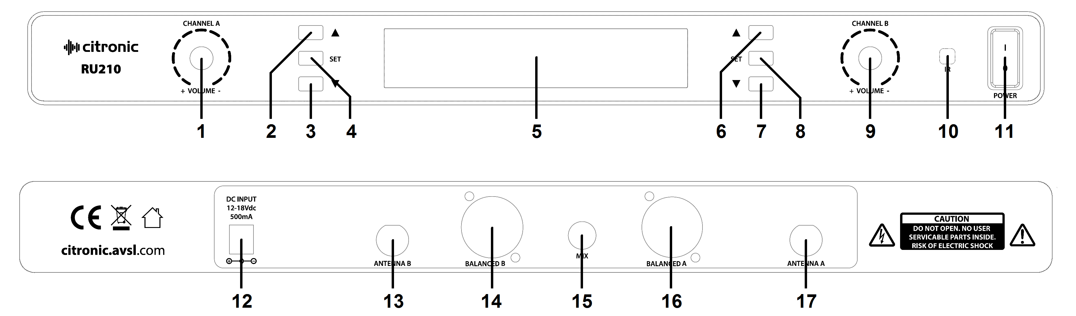
Receiver
| |
| |
|---|
| 1. | Channel A output volume control | 10. | IR sync sender |
| 2. | Channel A Group/Channel setting up | 11. | Power on/off switch |
| 3. | Channel A Group/Channel setting down | 12. | DC power in jack (5.5 x 2.1mm) |
| 4. | Channel A Group/Channel set | 13. | Antenna B connector (BNC) |
| 5. | LCD display | 14. | Channel B balanced XLRM output |
| 6. | Channel B Group/Channel setting up | 15. | Mix A+B unbalanced 6.3mm jack output |
| 7. | Channel B Group/Channel setting down | 16. | Channel A balanced XLRM output |
| 8. | Channel B Group/Channel set | 17. | Antenna A connector (BNC) |
| 9. | Channel B output volume control | | |
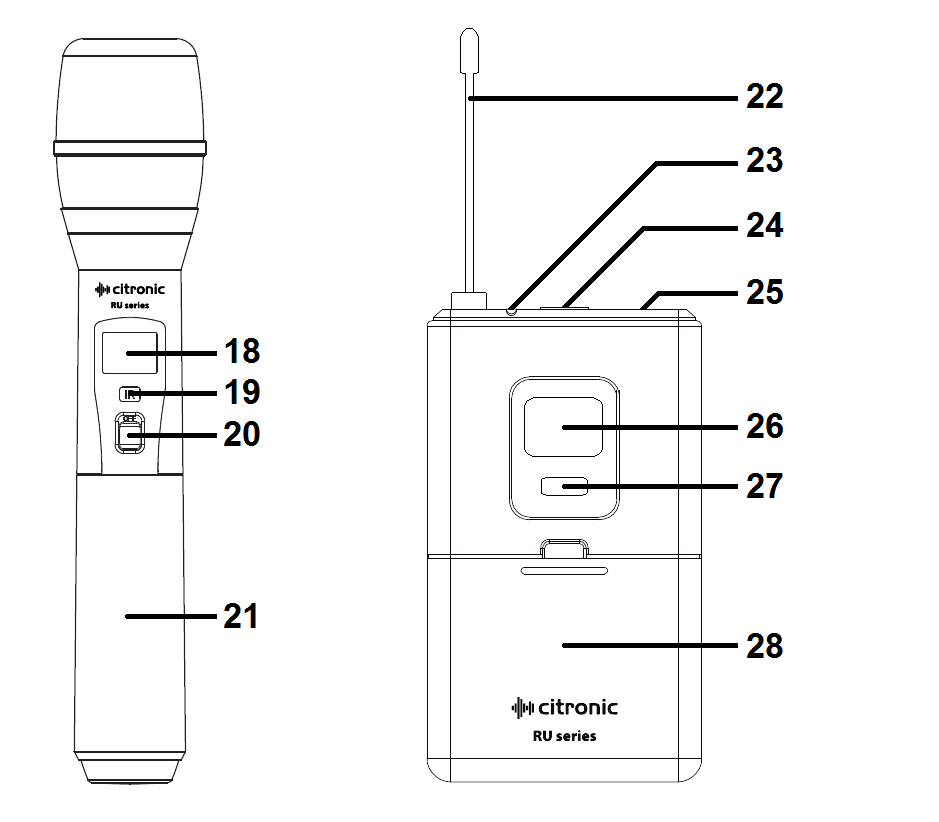
Transmitters
| |
|---|
| 18. | LCD display |
| 19. | IR sync detector |
| 20. | On/off switch |
| 21. | Battery compartment |
| 22. | Antenna |
| 23. | On indicator |
| 24. | Off – Mute – On switch |
| 25. | 3.5mm threaded jack socket |
| 26. | LCD display |
| 27. | On/off button |
| 28. | Battery compartment |
Setting Up
Insert the supplied AA batteries into each of the transmitters by carefully unscrewing the base of the handheld microphone or opening the flap of the bodypack to reveal the battery compartment. Insert the batteries (ensuring that + and - are the correct way round for each cell) and carefully replace each cover.
For neckband or lavalier microphones, connect the 3.5mm jack into each of the bodypacks, screwing the threaded jack securely into the socket.
The receiver antennas may be connected directly to the BNC connectors on the rear panel or alternatively front-mounted on rack ears.
If the receiver is to be rack-mounted, place the supplied rack ears against each side of the receiver and fix securely with 2 screws in each. These rack ears have holes for front-mounting the antennas and BNC extension leads for fixing into the holes. These should be connected to the BNCs on the rear panel, creating front sockets for the antennas to connect onto.
A choice of mixed output of both microphones on 6.3mm jack or individual balanced XLR outputs is available on the rear panel of the receiver. Connect the jack or XLR (optional) leads to the relative output connector(s), turn down the volume of any equipment (mixer, amplifier etc.) that the signal will be fed into and then connect the jack or XLRs to the equipment.
Position the receiver within the best available line of sight to the transmitters and connect the DC jack of the supplied power adaptor to the receiver and the plug-top to the mains outlet.
Operation
Turn microphone levels down on the receiver and switch on power on the front panel of the receiver.
Warning! - take care not to point microphones towards speakers – this can cause damaging feedback (loud whistle or howling noise) – try to point microphones away from the speaker cabinets.
For the handheld version, move the switch on each handheld transmitter upward to switch it on and the LCD display should light for a few seconds, showing the carrier frequency and battery status.
For bodypack transmitters, press and hold the front on/off button until the display lights up briefly, ensuring that the Mute switch is off. Displays will show the current carrier frequency and battery status. Transmitter frequencies should match those on the receiver. If not, see “Tuning” below.
Gradually increase the microphone level on the receiver, then increase the volume on the mixer or amplifier until the sound from each microphone can be heard through the equipment.
Tuning
For each microphone, the carrier frequency may be selected on the receiver unit by pressing the SET button twice, which causes the GROUP label to flash in the display. The ▲ and ▼ buttons can be used to select the Group from 1 to 7. Pressing the SET button again causes the CHANNEL label to flash. The channel can be selected within a group using the ▲ and ▼ buttons. Tuning microphone A to a particular channel will mean that the same channel cannot be selected for microphone B and vice versa.
Groups 1 to 6 have between 3 and 5 preset channels, whilst Group 7 allows access to all 81 possible frequencies. Depending upon any other radio signals in the vicinity of the operating environment, one particular Group may offer a better channel spacing than another and this should be determined by experimentation. If a particular group of frequencies results in poor reception or interference, try another or use Group 7 to manually select carrier frequencies in 25kHz steps.
Once a channel is selected, press SET to accept the channel and press SET again to transmit the IR sync signal (animated lines will show next to IR in the display). Hold the IR detector on the handheld microphone or inside the bodypack battery compartment up to the IR sender on the main unit to sync the carrier frequency to the transmitter.
In Use
Switching on each transmitter will open up the radio carrier frequency to the receiver and also send a pilot tone frequency, which is not audible but is used by the receiver to open the audio channel. This system helps to avoid any spurious radio frequencies interfering with the wireless microphone signal.
When the transmitter’s RF signal is recognized by the receiver, an RF meter will show the carrier signal strength in the LCD display. Likewise, speaking into the microphone will send audio over this carrier and an AF volume meter will show the audio level in the LCD display.
For neckband or lavalier microphones, there is also a mute switch on the top of each bodypack, which can be used to temporarily cut the microphone output whilst maintaining the carrier frequency. This may be useful to silence the mic whilst moving across the front of speakers or as a standby setting.
In addition, each bodypack has a Gain adjustment inside the battery compartment to match the gain level for the type of neckband or lavalier microphone that is connected to it.
If the wireless system is to be out of use for longer than a few seconds, it is preferable to switch the transmitter off, which mutes the audio, deactivates the radio carrier signal and powers down the transmitter. Be sure to turn down the volume of the mixer or amplifier before switching off the receiver.
Unplug signal leads from the receiver and mixer or amplifier when moving or packing away.
If the system is not to be used for long periods of time, remove the batteries from the transmitters and unplug the power adapter from the receiver and the mains outlet.
Folding away or removing the antennas can also help avoid damage when the system is not in use.
