Z44R Multi-purpose 1U Mixer
Adastra Z44R multi-purpose rack mixer has been designed to offer a versatile and wide range of
functions to meet many different applications. In order to achieve the
best results from this equipment and avoid damage through misuse, please
read and follow these instructions and retain for future reference.

Front Panel
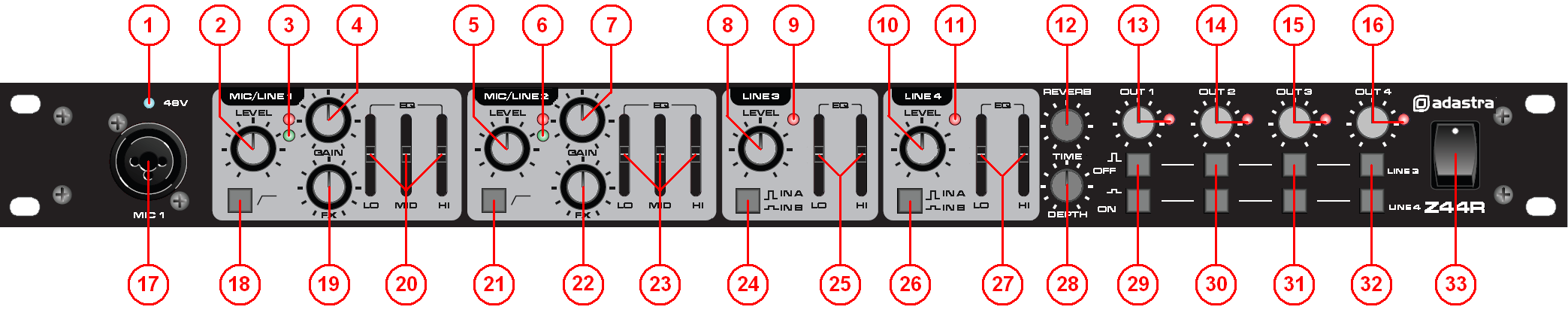
1. 48V phantom power LED indicator
2. MIC/LINE 1 LEVEL control
3. MIC/LINE 1 signal and peak LEDs
4. MIC/LINE 1 GAIN control
5. MIC/LINE 2 LEVEL control
6. MIC/LINE 2 signal and peak LEDs
7. MIC/LINE 2 GAIN control
8. LINE 3 LEVEL control
9. LINE 3 peak LED
10. LINE 4 LEVEL control
11. LINE 4 peak LED
12. REVERB TIME parameter control
13. OUT 1 level control & peak LED
14. OUT 2 level control & peak LED
15. OUT 3 level control & peak LED
16. OUT 4 level control & peak LED
17. MIC/LINE 1 combo input
18. MIC/LINE 1 low-cut rumble filter
19. MIC/LINE 1 FX level control
20. MIC/LINE 1 EQ sliders
21. MIC/LINE 2 low-cut rumble filter
22. MIC/LINE 2 FX level control
23. MIC/LINE 2 EQ sliders
24. LINE 3 source select switch
25. LINE 3 EQ sliders
26. LINE 4 source select switch
27. LINE 4 EQ sliders
28. REVERB DEPTH control
29. OUT 1 line selectors
30. OUT 2 line selectors
31. OUT 3 line selectors
32. OUT 4 line selectors
33. Power ON/OFF switch
Rear Panel
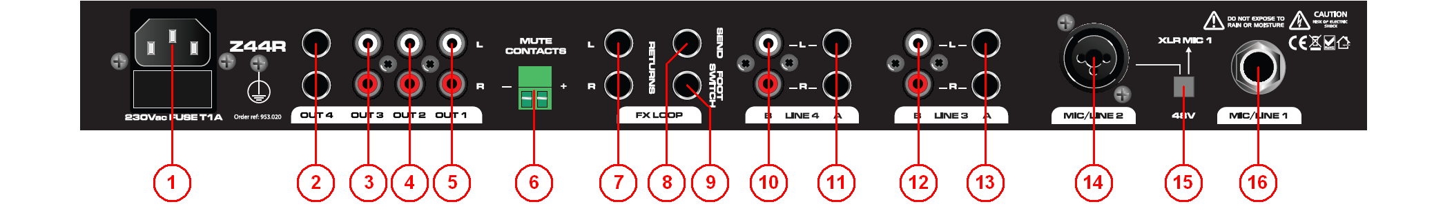
1. IEC mains inlet
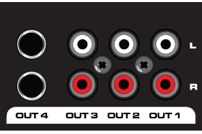
2. OUT 4 jack outputs L+R
3. OUT 3 RCA outputs L+R
4. OUT 2 RCA outputs L+R
5. OUT 1 RCA outputs L+R
6. MUTE CONTACTS for emergency systems
7. FX LOOP RETURNS jacks L+R
8. FX LOOP SEND jack
9. REVERB or FX LOOP FOOT SWITCH jack
10. LINE 4 B input RCAs L+R
11. LINE 4 A input jacks L+R
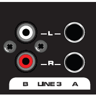
12. LINE 3 B input RCAs L+R
13. LINE 3 A input jacks L+R
14. MIC/LINE 2 combo input
15. 48V phantom power switch
16. MIC/LINE 1 rear jack input
Application
The Z44R can be configured to serve a variety of applications. Deciding
upon the particular setup should be the first step in order to ensure
all signal leads are connected properly. Some suggested combinations are
shown below.
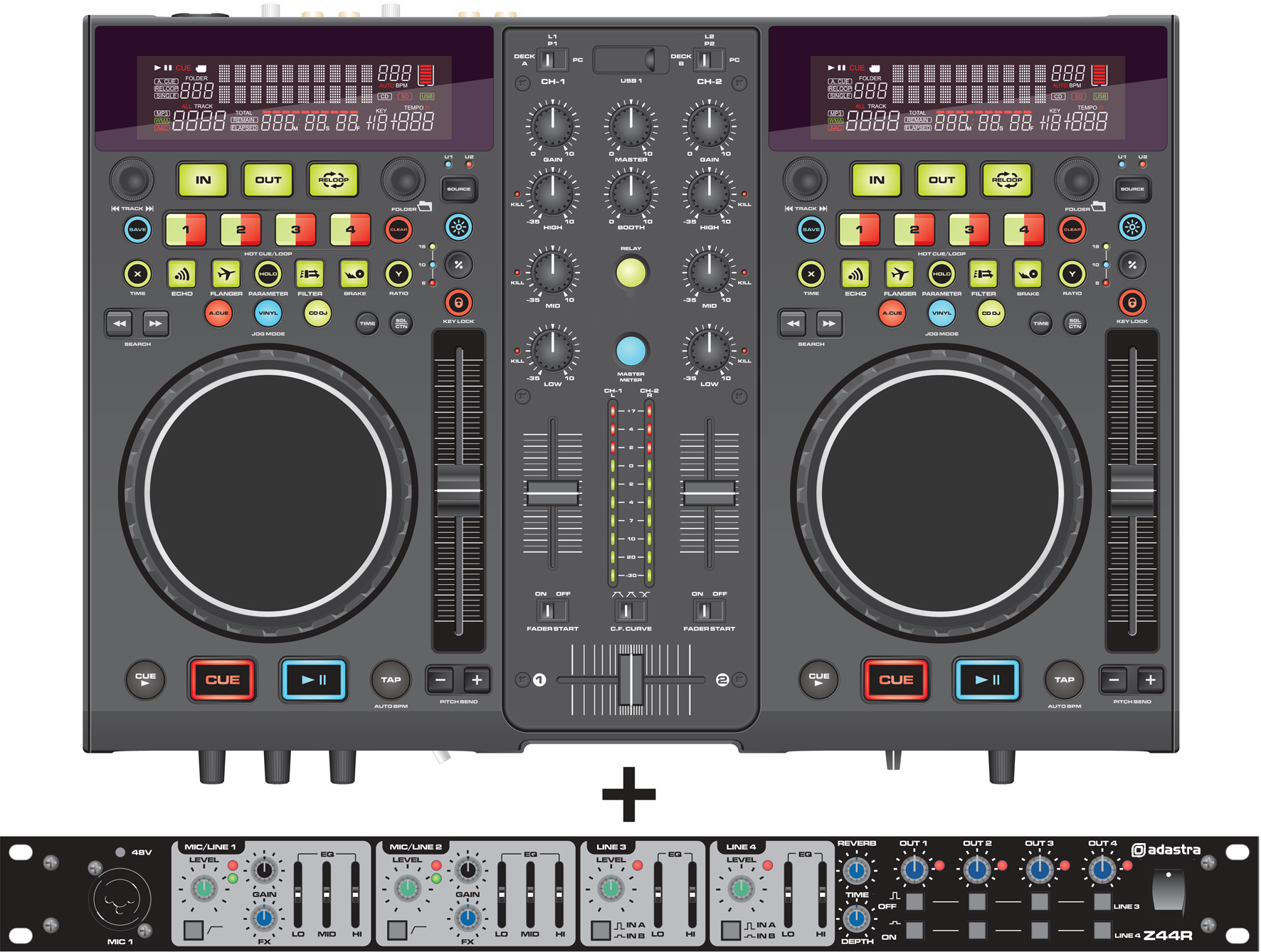
- DJ Add-on Vocal Mixer.
For DJs who want the option to host karaoke events, the Z44R
offers 2 extra microphone channels with genuine DSP reverb effect
and 2 extra switchable line sources (for laptop, CD+G players, MP3
players etc).
Adding these extra features takes up just 1U of rack space and can
be configured as a sub-mixer into the main DJ console or as the main
mixer to offer more stereo outputs…
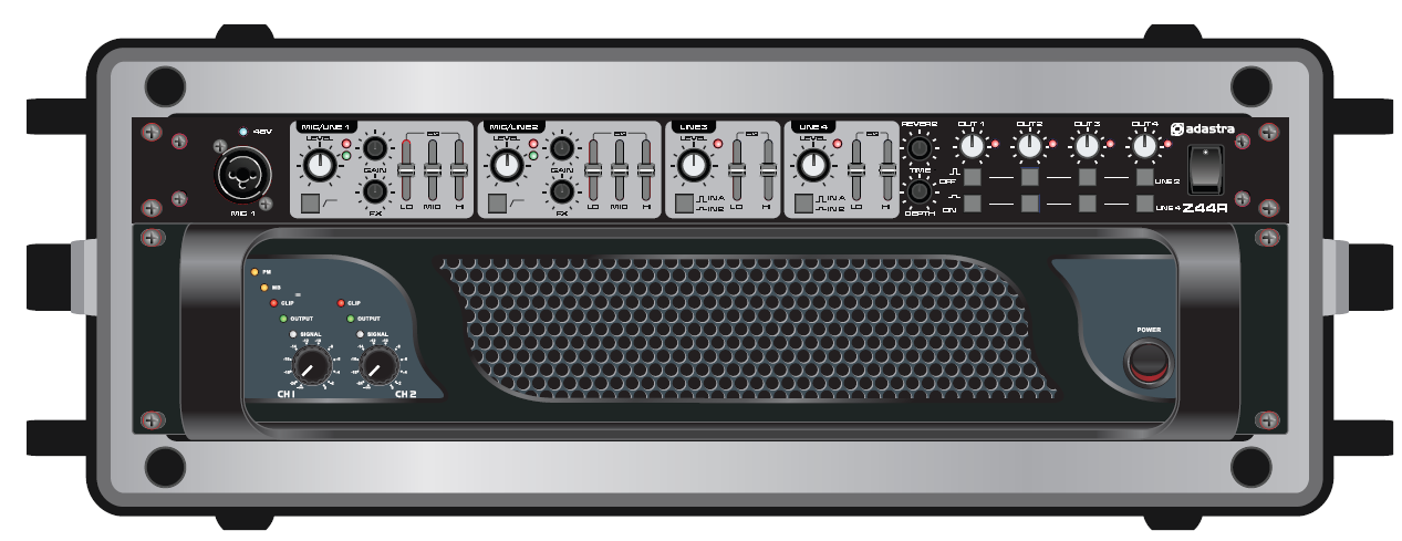
- Compact PA Head.
The Z44R can be rack-mounted in combination with a power amplifier
and/or a wireless receiver to form a PA head for driving passive
speaker cabinets. This keeps the format extremely compact for
solo/duo performers who only require 2 microphone inputs and up to 2
stereo sources up to whatever power is needed…
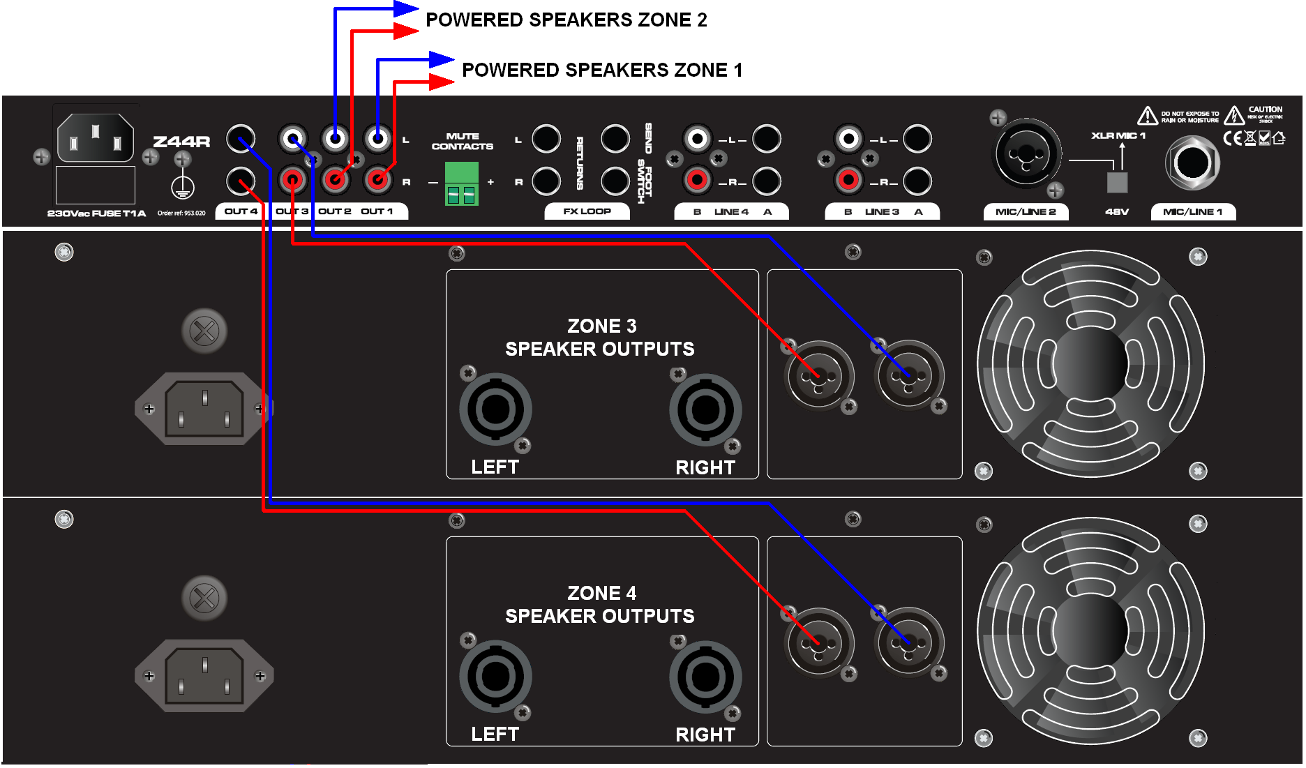
- Zoning Installation. The Z44R can operate as the main control for a venue
installation, feeding up to 4 stereo zones. Both microphone
inputs feed to all outputs (for public address and emergency
announcements), whereas the 2 line channels are switchable per zone…
Connection
 Before connecting to amplifier or other equipment,
turn down all volume controls to avoid loud noises which may cause
damage to other equipment. Always switch amplifier power on last in line
with volume levels down.
Before connecting to amplifier or other equipment,
turn down all volume controls to avoid loud noises which may cause
damage to other equipment. Always switch amplifier power on last in line
with volume levels down.
Use good quality 6.3mm jack signal leads to connect OUT 4 outputs from
the mixer to the amplifier or powered speaker(s). Further zones or
outputs can be served by connecting OUT 1, 2 and 3 to other amplifiers
or active speakers using good quality RCA leads.
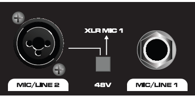
 Connect microphones, DI boxes
and other balanced low impedance audio inputs to the MIC/LINE combo
inputs using good quality XLR leads. Alternatively, connect high
impedance and line level signals to the combo inputs using 6.3mm jack
leads. (+ additional rear jack input for MIC/LINE 1). If phantom power
is to be used for condenser mics, press “+48V” switch and connect using
balanced XLR cables.
Connect microphones, DI boxes
and other balanced low impedance audio inputs to the MIC/LINE combo
inputs using good quality XLR leads. Alternatively, connect high
impedance and line level signals to the combo inputs using 6.3mm jack
leads. (+ additional rear jack input for MIC/LINE 1). If phantom power
is to be used for condenser mics, press “+48V” switch and connect using
balanced XLR cables.
Connect stereo line level sources to the LINE 3 and LINE 4 channels via
the Left + Right Jack or RCA connections on the rear panel. These can be
switched, offering a selection of 2 sources for each channel.
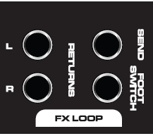

If the internal DSP reverb effect is to be operated remotely, connect a
latching foot switch to the rear panel F/S jack. Alternatively, this can
switch the feed from an external unit, which should be connected via the
FX LOOP. To do this, connect a jack lead from the SEND to the external
effect unit and its left & right outputs to RETURN L+R.
In an installation scenario, building regulations may require the sound
system to be muted if the fire alarm is triggered. The green MUTE
contacts on the rear panel will kill all channels except MIC 1 if the
contacts are shorted. This can be patched in to the venue fire alarm
panel to kill all music in the event of a fire, leaving the main
microphone active for emergency announcements.
Operation
- MIC/LINE channels 1 and 2:
Turn all MIC level and LINE LEVEL controls to minimum (2, 5, 8
& 10).
Set LO, MID and HI (20 & 23)controls to the centre position and
turn FX down (19 & 22).
Switch on the power on the right side of the front panel. (33).
Check each microphone input, gradually increasing GAIN (4 & 7)
until the red Peak LED flashes (3 & 6) and then back off the
GAIN until only the green Signal LED lights up.
Gradually turn up the OUT volume controls (13, 14, 15 & 16) part
way.
Increase the MIC/LINE 1 and 2 LEVEL controls (2 & 5) to the
desired level, taking care to avoid distortion or feedback from
the microphones.
Adjust LO, MID and HI controls to set the desired bass, middle and
treble content for each MIC/LINE input.
If effects are to be used, temporarily unplug the foot switch (if
used) and increase the DEPTH control (28) on the front panel.
Gradually turn up the FX control(s) (19 22) for the relevant
MIC channel(s) and adjust the TIME (12) control to set the
desired length of reverb effect. Plug the footswitch back in and
use to switch the effect in/out.
For some microphones, it can be beneficial to “roll-off” the very
low frequencies caused by handling and vibration to the microphone
body. If required, press in the Lo-cut Rumble Filter switch (18
& 21) on the microphone channel to reduce this type of noise.
- Stereo LINE channels 3 and 4:
For LINE 3 and 4 channels, check which pair of inputs the signal is
plugged into - jack (A) or RCA (B) – and set accordingly via the
Source Select switches (24 & 26) on the front panel.
Press in all of the OUT line selectors (29, 30, 31 & 32).
Set HI and LO controls (25 & 27) to the centre position.
Play the stereo line signal into the relevant channel and increase
the LEVEL (8 & 10) control as required.
Adjust HI and LO controls to set the desired bass and treble content
of the stereo line channels.
- Stereo OUTs 1 - 4:
Adjust the OUT volume controls (13, 14, 15 & 16) so that the red
Peak LEDs do not light constantly.
Press out any line selectors (29, 30, 31 & 32) for any
stereo inputs which are not required to be fed through any output
(MIC/LINE inputs are always fed to all outputs).
