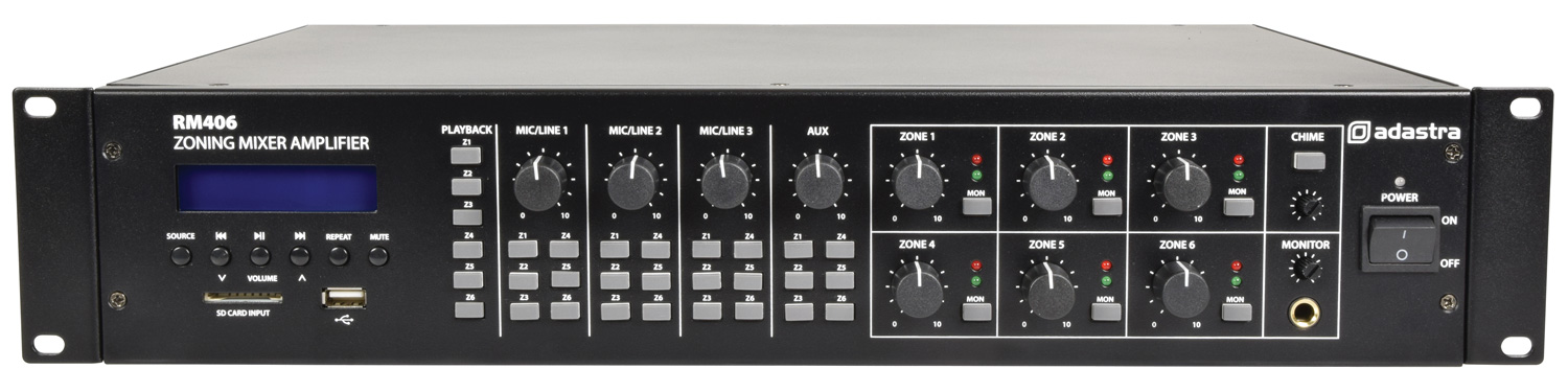
The Adastra RM406 rackmount 6-zone
mixer-amplifier is
designed to offer high quality, dependable service for mobile and
installed systems.
The RM406 is a versatile and powerful mixer amplifier with 4 input
channels which can be assigned in a matrix to any of 6 zone outputs. In
addition to external signal sources, the RM406 has and integrated
Bluetooth® receiver, FM tuner and USB/SD audio player for
comprehensive audio playback options.
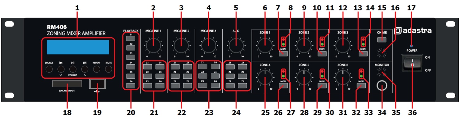
Front Panel
|
|
|
|
| 1. |
Media player |
19. |
USB port |
| 2. |
Mic/Line 1 level control |
20. |
Media playback zone assign buttons |
| 3. |
Mic/Line 2 level control |
21. |
Mic/Line 1 zone assign buttons |
| 4. |
Mic/Line 3 level control |
22. |
Mic/Line 2 zone assign buttons |
| 5. |
Auxiliary line input level control |
23. |
Mic/Line 3 zone assign buttons |
| 6. |
Zone 1 output level control |
24. |
Auxiliary line input zone assign buttons |
| 7. |
Zone 1 monitor send button |
25. |
Zone 4 output level control |
| 8. |
Zone 1 output LED indicators |
26. |
Zone 4 monitor send button |
| 9. |
Zone 2 output level control |
27. |
Zone 4 output LED indicators |
| 10. |
Zone 2 monitor send button |
28. |
Zone 5 output level control |
| 11. |
Zone 2 output LED indicators |
29. |
Zone 5 monitor send button |
| 12. |
Zone 3 output level control |
30. |
Zone 5 output LED indicators |
| 13. |
Zone 3 monitor send button |
31. |
Zone 6 output level control |
| 14. |
Zone 3 output LED indicators |
32. |
Zone 6 monitor send button |
| 15. |
Chime button |
33. |
Zone 6 output LED indicators |
| 16. |
Chime output level control |
34. |
Monitor headphones output |
| 17. |
Power indicator |
35. |
Monitor output level control |
| 18. |
SD card slot |
36. |
Power on/off switch |
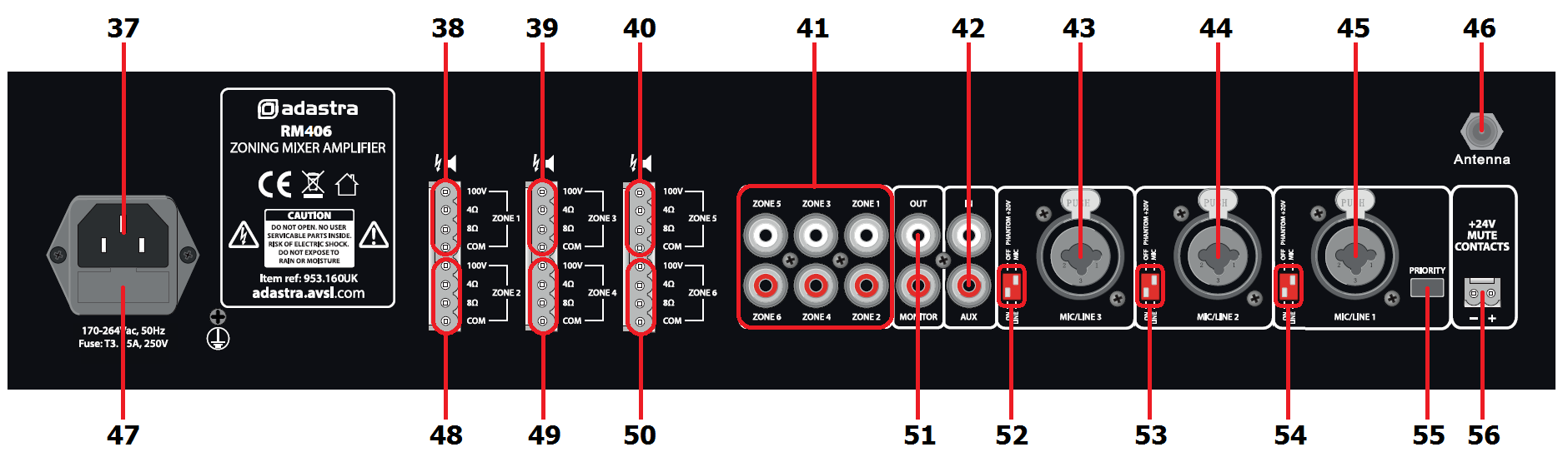
Rear Panel
|
|
|
|
| 37. |
Voltage selector |
47. |
Mains power inlet (IEC) and fuse holder |
| 38. |
Zone 1 speaker output terminals |
48. |
Zone 2 speaker output terminals |
| 39. |
Zone 3 speaker output terminals |
49. |
Zone 4 speaker output terminals |
| 40. |
Zone 5 speaker output terminals |
50. |
Zone 6 speaker output terminals |
| 41. |
Zones 1-6 line level outputs (RCA) |
51. |
Monitor line level output (2 x RCA) |
| 42. |
Channel 4 Auxiliary input (2 x RCA) |
52. |
Channel 3 DIP switches (mic/line + phantom) |
| 43. |
Channel 3 Mic/Line input (XLR/jack) |
53. |
Channel 2 DIP switches (mic/line + phantom) |
| 44. |
Channel 2 Mic/Line input (XLR/jack) |
54. |
Channel 1 DIP switches (mic/line + phantom) |
| 45 |
Channel 1 Mic/Line input (XLR/jack) |
55. |
Channel 1 priority switch |
| 46. |
Antenna connection |
56. |
24V emergency mute contacts |
Connection and Setup
With the RM406 power switched off (36), connect the rear IEC inlet (47)
to the mains using the supplied mains lead (or an equivalent approved
type). Ensure that the voltage is correct as indicated on the voltage
selector (37) and that the mains outlet is switched on.
The RM406 has 4 input channels and an integral multi-source audio
player.
Channels 1, 2 and 3 are designed for either microphones or line level
sources (such as a CD/mp3 player or output from a mixer) via combo
connectors on the rear panel.
These can accept either XLR or 6.3mm plugs for balanced or unbalanced
signals.
DIP Switches
 Mic/Line inputs 1, 2 and 3 each have 2 DIP switches
on the rear panel (52, 53, 54) to set the input level and/or activate
+20V phantom power for use with condenser microphones.
Mic/Line inputs 1, 2 and 3 each have 2 DIP switches
on the rear panel (52, 53, 54) to set the input level and/or activate
+20V phantom power for use with condenser microphones.
Set the level correctly for the type of input source connected (Mic or
Line)
If the source connected is a condenser microphone which requires phantom
power, make sure that the phantom is switched on for that channel.
Be sure to make these DIP switch settings when the amplifier is switched
off. Making any changes when the amplifier is powered up may cause loud
bangs through the system which can damage the speakers.
Priority and Emergency Activation
The Mic/Line 1 input also has a Priority switch (55), which attenuates
all other channels when Mic/Line 1 signal is detected and returns them
to normal when Mic/Line 1 signal is silent.
For buildings with a main emergency alarm panel (for fire alerts etc.),
the RM406 has Mute contacts on the rear panel (46), which will mute all
audio except for channel 1 when activated by a 24V trigger voltage.
This leaves channel 1 active for evacuation announcements in the case of
an emergency.
(The 24V contacts can be connected with either polarity +/- or -/+ to
operate)
The screw terminal plug can be pulled out to make connection easier.
2-core bell wire is appropriate for this.
Connect a 24Vdc output from the alarm control panel observing the
correct polarity shown on the contacts.
Signal Inputs and Outputs
Connect microphones or line signals to Mic/Line 1, 2 and 3 inputs (43,
44, 45) using good quality signal leads.
A stereo or mono line level source can be connected to the Auxiliary
channel 4 input on 2 RCA connectors (42)
For checking the output of any zone, an assignable Monitor output can be
connected to headphones from the front panel 6.3mm jack (34) or as a
line output (e.g. to active speakers) from RCA connectors at the rear
(51)
Each zone output has a dedicated RCA signal output on the rear panel
(41), which can be connected to the line inputs of active speakers or
amplifiers. These are in addition to the speaker outputs detailed below.
An antenna input (46) is provided on the rear panel for connection to an
external aerial for FM tuning.
Speaker Outputs
The RM406 has a separate speaker output for each zone, connected via 3
large modular terminal plugs.
Each plug can be removed from the rear panel for convenient connection
of speaker outputs to 2 zones.
Each zone output can be used to power either 100V line speakers or
standard low impedance speakers.
These 2 configurations cannot be used together, so it is important to
decide which will be used at the start.
100V Line Systems
For 100V speakers, connect the selected zone output to the first speaker
in the zone using double-insulated speaker wire which has adequate
current rating to handle the total output of the amplifier.
Connect the “100V” output terminal for the selected zone to the positive
(+) connection of the speaker and “COM” output to the negative (-)
connection of the speaker. Connect further speakers in parallel to the
first speaker with all positive terminals and connected together and all
negative terminals connected together as shown below.
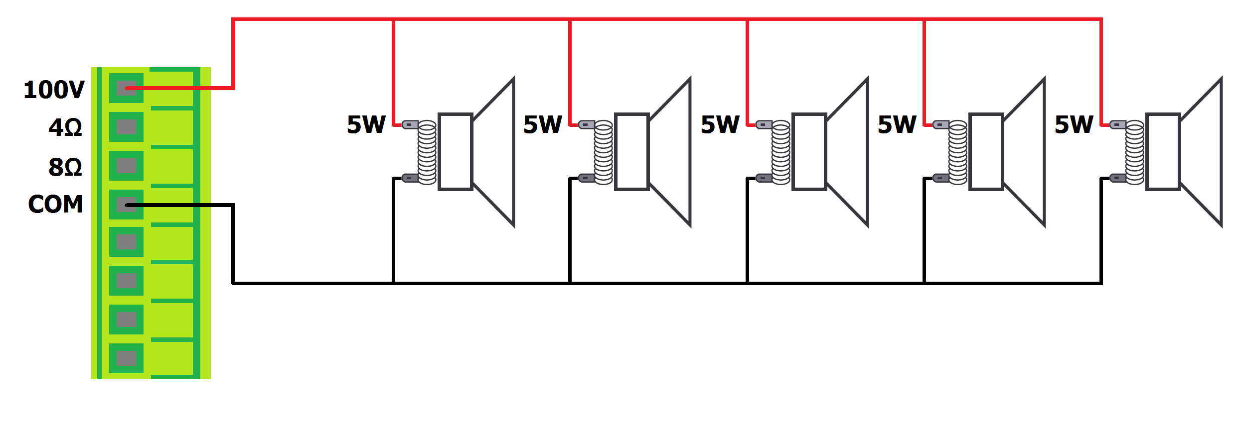
A 100V line speaker system can comprise of many speakers connected
together. The determining factor for how many speakers can be used on a
single amplifier is the power rating. For most purposes, it is advised
to connect as many speakers as needed with a combined wattage of no more
than 90% of the amplifier’s output power rating (in the case of the
RM406, this is 40W per zone output)
The terminals of a 100V speaker are connected via a transformer and if
necessary, this transformer may be “tapped” for different power ratings.
These tappings can be used to adjust the wattage (and output volume) of
each speaker in a zone to help achieve the ideal total power of the
system for the relevant zone output.
Low Impedance Systems
Alternatively, each zone output of the RM406 is capable of powering one
or more low impedance speakers.
There is an option on each zone for either a 4Ω or 8Ω speaker output to
determine the minimum impedance.
It is essential to select the correct output terminal when opting for
low impedance speakers.
For a single 8Ω speaker, connect the positive (+) wire to the “8Ω”
terminal and the negative (-) wire to “COM”
For a single 4Ω speaker or for 2 x 8Ω speakers connected in parallel,
connect the positive (+) wire to the “4Ω” terminal and the negative (-)
wire to “COM”
In either case, the connected load should have a combined impedance no
lower than stated on the terminal.
Lower impedance may cause irreparable damage to the amplifier.
The connected speaker(s) must also have a power handling to accept up to
40Wrms from the zone output.
Lower power handling may risk damage to the speakers.
Operation
When all connections to the amplifier are made, turn all rotary controls
down and switch on the power (36) and the power LED (17) will
illuminate.
To check for correct operation of the system, select an input source and
output zone for testing.
In the following example, Mic/Line 1 input and Zone 1 output have been
selected.
Turn up Zone 1 level control (6) part way for testing
Make sure that the “Z1” assign button for Mic/Line channel 1 (21) is
pressed in
If a line input is connected to channel 1, make sure that the signal
is playing from the audio source
If a microphone is connected to channel 1, speak into the microphone
Gradually turn up the Mic/Line 1 level control (2) whilst checking
for output to Zone 1
Increase the Zone 1 output level to the maximum required volume for
that zone
Reduce the Mic/Line level to compensate
If Zone 1 cannot be heard from the location of the RM406, use the
monitoring feature as follows
Turn down the Monitor level control (35) and connect headphones to
the Monitor output (34)
Make sure that the Monitor button for Mic/Line 1 is pressed in and
listen through the headphones
Gradually turn up the Monitor level control and check for the output
to Zone 1
Each zone output has 2 LED indicators to show the signal status (8, 11,
14, 27, 30, 33)
The green LED follows the audio to show that the signal is present.
If the red LED lights for more than very short flashes, this indicates
overload to that zone.
In this instance, the zone level control should be reduced until the red
LED does not light.
The above process can be extended to check all zones and other input
channels can be checked in the same way as for Mic/Line 1 (note: in the
case of Aux channel 4, this can only accept line level input)
If preferred, the system can be checked using the onboard multi-source
audio player.
Full information on the operation of this feature is detailed below.
Onboard Multi-Source Audio Player
The RM406 is fitted with a built-in audio player, operated via a backlit
LCD display and transport buttons.
This section provides access to a Bluetooth receiver, FM radio tuner and
USB/SD audio player
In order to play audio to one of the zones, it is necessary to press in
one of the “Playback” buttons (20).
|
|
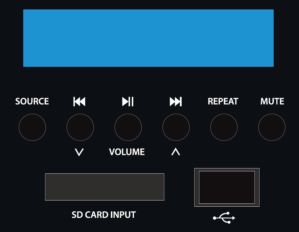
| SOURCE |
Select between Bluetooth, FM tuning, USB or SD playback | |
|
Previous track or FM channel select |
|
Play/Pause track or FM auto tuning |
|
Next track or FM channel select |
| REPEAT |
Select RT1 repeat single, RTA repeat all or RND random |
| MUTE |
Mute playback (press and hold to switch the player on/off) |
When the RM406 is powered up, the media player display will illuminate
with an initial greeting “Welcome”.
This message will then change to show the mode, output volume and media
status.
If no USB or SD media are connected, the initial mode of the audio
player will be Bluetooth.
Bluetooth
The Bluetooth function allows connection of a smart phone or tablet to
the media player section for playback of stored files or streamed
digital audio. It will be necessary to pair the device to the receiver
as follows.
Open the Bluetooth settings menu on the smart phone or tablet (or
other sending device)
Scan for Bluetooth devices and look for “adastra 0000” in the list
of available devices
(ensure that the RM amp is powered on and within reception range)
Select “adastra 0000” and the sending device should confirm that it
is connected as an audio device. (note that “0000” may be a
different number if it has been edited – see below)
Play audio from the sending device, ensuring that volume controls
are not turned down/muted
Turn up the LN5/USB volume control on the amplifier to the required
level.
The Previous, Next and Play/pause buttons will operate in Bluetooth as
remote playback controls. Holding the Previous track or Next track
buttons (29, 31) will adjust the output volume of the player.
The Bluetooth name can be customized to enable identification of
individual nearby amplifiers.
To customize the Bluetooth number press and hold the Play/Pause button
until adastra 0000 is displayed with one of the characters flashing.
Press Previous or Next buttons to edit the number and Play/Pause to
select another character. Hold Play/Pause to store the ID and exit.
Note: Android devices have the facility to re-name devices within the
Bluetooth settings menu.
If the Bluetooth ID has been re-named on the Android device, editing the
Bluetooth ID on the media player will not affect the name displayed on
that Android device.
FM Tuner
Press the Source button to switch to the FM tuner function. For good FM
reception, it will be necessary to connect an external aerial to the
Antenna connector on the rear panel using good quality coaxial RF cable
terminated with an F-type connector.
To auto-tune available stations, press and hold the Play/Pause button to
begin auto tuning, which scans available stations and automatically
stores them as channels within the FM tuner.
Alternatively, to tune the station presets manually, press the
Play/Pause button briefly to enter manual tuning mode (MANU). Use
Previous/Next track buttons to select the desired frequency and press
REPEAT, then use Previous/Next track buttons to select the preset and
press REPEAT again to store the frequency in that preset (display will
show “OK”). Repeat for all ten presets P01 to P10. Press MUTE to exit
the manual tuning mode.
To step through pre-set stations, press the Previous or Next buttons.
Hold down the REPEAT button to delete a stored station.
Holding the Previous track or Next track buttons will adjust the output
volume of the player.
USB/SD Player
The RM406 audio player has inputs for a USB pen drive or SD card with
standard compressed digital audio files on them. Inserting either or
both of these will switch the player to read from these sources and the
display will show “Music Mode”.
Whichever device is connected last will take priority and playback will
start from that source. The display will show the source selected, track
number, repeat mode, volume level and track name (scrolling for longer
text).
Pressing the Source button will now step through Bluetooth, FM and
either or both USB and SD media.
If the selected media had been playing previously, selecting it again
will return to the last point played.
Pressing play/pause will play or pause the selected track. The Mute
button will mute or un-mute the output.
Pressing Previous or Next buttons will select through audio files on the
selected media.
Pressing the Repeat button will select through 3 modes. Repeat All
tracks, repeat single track or random play.
