The Adastra A8 rackmount tri-stereo amplifier is designed to offer
high quality, dependable service for mobile and installed systems.
Please read this manual fully and follow the instructions to achieve the
best results with your new purchase and to avoid damage through misuse.
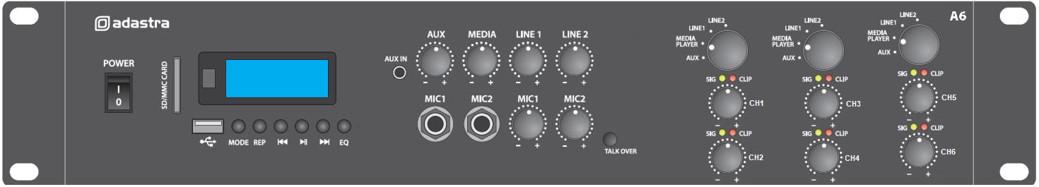
Front Panel
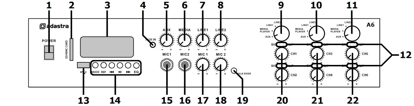
1. Power on/off switch
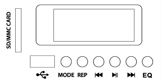
2. SD card slot
3. Media player display
4. 3.5mm stereo Aux input
5. Aux input volume control
6. Media player volume control
7. Line 1 input volume control
8. Line 2 input volume control
9. Stereo input selector CH.1+2
10. Stereo input selector CH.3+4
11. Stereo input selector CH.5+6
12. Output Signal & Clip indicators
13. USB port
14. Media player control panel
15. Mic 1 input 6.3mm jack
16. Mic 2 input 6.3mm jack
17. Mic 1 volume control
18. Mic 2 volume control
19. Talkover on/off button
20. CH.1 & CH.2 output level
21. CH.3 & CH.4 output level
22. CH.5 & CH.6 output level
Rear Panel
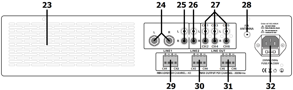
23. Ventilation grille (do not obstruct airflow)
24. Line 1 input (L+R 6.3mm jack)
25. Line 1 input (L+R RCA)
26. Line 2 input (L+R RCA)
27. Line outputs CH.1+2, CH.3+4, CH.5+6 (RCA)
28. FM antenna connection (F type)
29. CH.1 + CH.2 speaker outputs – Euroblock terminal
30. CH.3 + CH.4 speaker outputs – Euroblock terminal
31. CH.5 + CH.6 speaker outputs – Euroblock terminal
32. IEC mains inlet & fuse holder
Speaker Connections
The A6 has 6 speaker output channels (CH.1-6) arranged as 3 x Left and
Right stereo output terminal blocks.
For each output, connect “–” to the “–” speaker terminal(s) and “+” to
the “+” speaker terminal(s)
Connect speakers with a combined impedance of no lower than 4Ω to each
output channel.
If the speakers being connected are 4Ω, then connect only 1 speaker
to each channel.
If the speakers are 8Ω, you can connect up to 2 speakers in parallel
to each channel.
If the speakers are 16Ω, you can connect up to 4 speakers in
parallel to each channel.
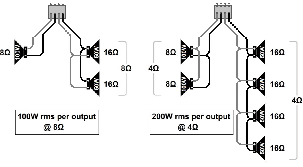 Some example wiring diagrams are shown opposite
with speakers connected in parallel.
Some example wiring diagrams are shown opposite
with speakers connected in parallel.
The impedance of the load measured in “Ohms” (Ω) will also determine the
power output.
The amplifier delivers its maximum power output at the minimum impedance
rating (4Ω). Higher impedances result in a lower output.
The combined load on each output shares the power from the amplifier. If
the amplifier is delivering 200W to 2 speakers connected in parallel
with the same impedance, they must each be capable of handling 100W.
Input Connections
The A6 has 2 microphone inputs to all outputs and 4 selectable stereo
sources per stereo output channel.
(one of which is the internal media player)
Connect wired microphone(s) to the Mic 1 and/or Mic 2 jack inputs
(6.3mm) on the front panel (15, 16)
The volume level of these is controlled by the Mic 1 and Mic 2 volume
controls (17, 18)
A smart phone, tablet or mp3 player can be connected to the Aux jack
(3.5mm) on the front panel (4)
The volume level of this stereo input is controlled by the AUX volume
control (5)
To hear this input through the speakers, “AUX” must be selected on the
relevant input selector (9, 10, 11)
On the rear panel, there are 2 further stereo line inputs for connecting
CD/DVD players, DVB/DAB tuners etc.
Line 1 input has a choice of Left + Right 6.3mm jack (24) or RCA inputs
(25)
The volume level of this input is controlled by the Line 1 volume
control (7)
To hear this input through the speakers, “LINE 1” must be selected on
the relevant input selector (9, 10, 11)
Line 2 has Left + Right RCA inputs (26)
The volume level of this input is controlled by the Line 2 volume
control (8)
To hear this input through the speakers, “LINE 2” must be selected on
the relevant input selector (9, 10, 11)
The mix of mic1+2 and selected line input can be fed to further
equipment via 3 stereo RCA Line outputs (27)
For good reception of FM radio stations (if needed) in the media player,
the A6 has an “F” connector on the rear panel (28) which can be
connected to an external FM antenna (aerial)
Connect the IEC power inlet (32) to the 230Vac mains supply, using the
IEC lead provided.
Operation
When all connections to the amplifier are made, turn all rotary controls
down and switch on the power (1) and the media player display will
illuminate.
Turn CH.1 - 6 rotary controls (20, 21, 22) up part way for testing.
If a microphone is connected to one of the mic inputs (15, 16) gradually
increase the volume control for that channel (17, 18) and speak into the
mic until it is heard through the speakers.
Alternatively, play a signal into one of the aux or line inputs (4, 24,
25, 26) and ensure it is selected on the relevant input selector (9, 10,
11) and turn up its volume control (5, 7, 8) until the signal is heard
through the speakers.
Note: Treat each pair of output channels as a stereo channel (i.e.
CH.1+2, CH.3+4, CH.5+6)
The same test applies for the internal media player (see section below)
by playing a track or radio station. Select “MEDIA PLAYER” on the
relevant input selector and gradually increase the media player volume
(6)
Turn up the CH.1 - 6 volume controls to the maximum required volume
level for each output and reduce the channel volume control if
necessary.
The output of each speaker channel is represented on the SIG and
CLIP LEDs (12) and care should be taken that the red CLIP LED is
only lit momentarily during use.
Anything longer than a short flash of the CLIP LED may be indicating
distortion or clipping of the output signal and the output channel
volume control should be turned down.
Any microphones connected should not be able to “hear” the speakers,
which can cause feedback (squealing or howling) and should not be
pointed towards the speakers. If this still happens, turn down the
volume for that microphone to reduce the feedback
If the TALKOVER feature (19) is switched on, speaking into the
microphone will “override” any audio playback from the selected stereo
Aux, Line or Media input, which will be reduced in volume temporarily.
This allows voice announcements to be heard without interference from
the line inputs or media player.
To avoid loud pops through the speakers, turn down the CH.1 - 6 volume
controls before powering down.
Media Player
The A6 amplifier is equipped with a multi-functional media player for
playback of audio files from USB or SD media, FM radio stations or
Bluetooth connection. Front panel controls are as described below.
|
|
| MODE |
Select between USB, SD, FM tuner & Bluetooth |
| REP |
Repeat mode – Random, One, Folder and All |
|
Previous track/FM station (hold for volume down) |
|
Play/Pause (Auto-tune in FM mode) |
|
Next track/FM station (hold for volume up) |
| EQ |
Select preset - Bass/Pop/Rock/Jazz/Classical/Normal |
USB/SD media playback
Insert USB or SD media containing mp3 tracks and playback should begin
automatically.
The stored tracks should be standard mp3 audio format. If playback does
not start, press MODE or Play/Pause button.
The display will initially show the track number and then an elapsed
time counter.
A USB or SD symbol will also be displayed to show which media is being
used.
Ensure MEDIA PLAYER is selected on the relevant output selector (9, 10, 11, 12) and turn up the MEDIA
volume control (6)
Tracks may be navigated by pressing for the previous track button and forward button for
the next track.
Press and hold previous track button to reduce the media player volume or press and hold
forward button buton to increase the volume.
Playback can be paused and resumed by pressing Play/Pause button.
Pressing REP sets the repeat mode: rAN= random, ONE= single track,
FOLd= folder, ALL= all tracks
Pressing EQ sets the preset:bAS= bass, POP= pop, rOC= rock, JAZ=
jazz, CLA= classical, NOr= normal
FM Tuner
The FM tuner function operates in the same way as a standard FM radio
and benefits from the connection of an FM antenna to the rear panel ‘F’
type connector.
Press the media player MODE button until the display shows a frequency
(e.g.”88.3MHz”)
If auto-tuning has already been performed, the display may show a
channel (e.g. “CH01”)
If no channels are tuned in, press the Play/Pause button to begin auto tuning,
which scans available stations and stores them as channels within the FM
tuner. Pressing Play/Pause button again will abort the auto-tuning.
To step through pre-set stations, press the Back or Forward buttons… CH01–
CH02– CH03– CH04 etc.
Press and hold Back button to reduce the FM radio volume or press and hold Forward button to
increase the volume.
Bluetooth
The Bluetooth function allows connection of a smart phone or tablet to
the media player section for playback of stored files or streamed
digital audio. To enable this function, it will be necessary to pair the
sending device to the receiver as follows.
Press the media player MODE button until the display flashes “bLUE”.
Open the Bluetooth settings menu on the smart phone or tablet (or
other sending device).
Scan for Bluetooth devices and look for “A series” in the list of
available devices.
(ensure that the A2 is powered on, Bluetooth mode is selected and
within reception range).
Select “A series” and the sending device should confirm that it is
connected as an audio device.
Play audio from the sending device, ensuring that volume controls
are not turned down/muted.
Select MEDIA PLAYER on the input selector and turn up the MEDIA control (6) to the required level.
The Back, Forward and Play/Pause buttons will operate in Bluetooth as remote playback
controls.
Holding the Back or Forward buttons will adjust the output volume of the player.
If the sending device goes out of range, connection should automatically
resume when back in range.
Likewise, if a different mode is selected, connection should resume when
Bluetooth mode is re-selected.
If Bluetooth is disabled on the sending device or paired to a different
receiver, it will be necessary to re-connect the sending device to the
A2 from step 2 above to re-establish a Bluetooth link.
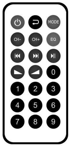
Media player remote control
In addition to front panel controls, the media player can be operated
via the supplied I.R. remote handset.
As supplied, the handset will have a plastic tab at the bottom to
preserve battery charge before first usage.
Remove this tab by pulling away from the handset to engage the battery
and activate the remote control.
If this needs to be replaced, the battery compartment can be slid out
from the bottom to reveal the cell.
Replace the battery with a CR2025 button cell.
Point the top of the remote control towards the media player display and
operate in line of sight.
Some of the controls on the remote handset mirror those on the front
panel and are described below.
|
|
 |
Media player power on/standby button |
 |
Repeat mode – select Random, One, Folder or All tracks |
| MODE |
Select USB, SD, FM tuner or Bluetooth mode |
| CH- / CH+ |
Select FM radio station |
| EQ |
Select preset EQ – Bass, Pop, Rock, Jazz, Classical or Normal |
|
Previous or Next track select |
|
Play / Pause track (auto-tune in FM tuner mode) |
|
Adjust media player volume down or up |
| 0 - 9 |
Direct track or channel access – key in number |
